

360
8 Secondary Ventilation
(i) Air velocity at the fan outlet (duct inlet).
(j) Dynamic pressure at the fan.
(k) Average airflow rate in the duct.
(l) Shock losses at the inlet cone of the fan (use X = 0.5).
(m) Shock losses at the fan screen (the screen has 85% porosity).
(n) Shock losses at the upstream silencer.
(o) Shock losses at the downstream silencer.
(p) Total friction losses in the duct.
(q) Friction losses at the joints.
(r) Shock losses at the elbow (use X = 0.5).
(s) Losses at the duct outlet (discharge).
(t) Return airflow pressure loss.
(u) Total pressure loss.
(v) Corrected total pressure loss.
(w) Size of the fan required.
(x) In this example, some parameters are above the expected normal values. Identify
them and indicate the consequences this has on the design.
Formulae:
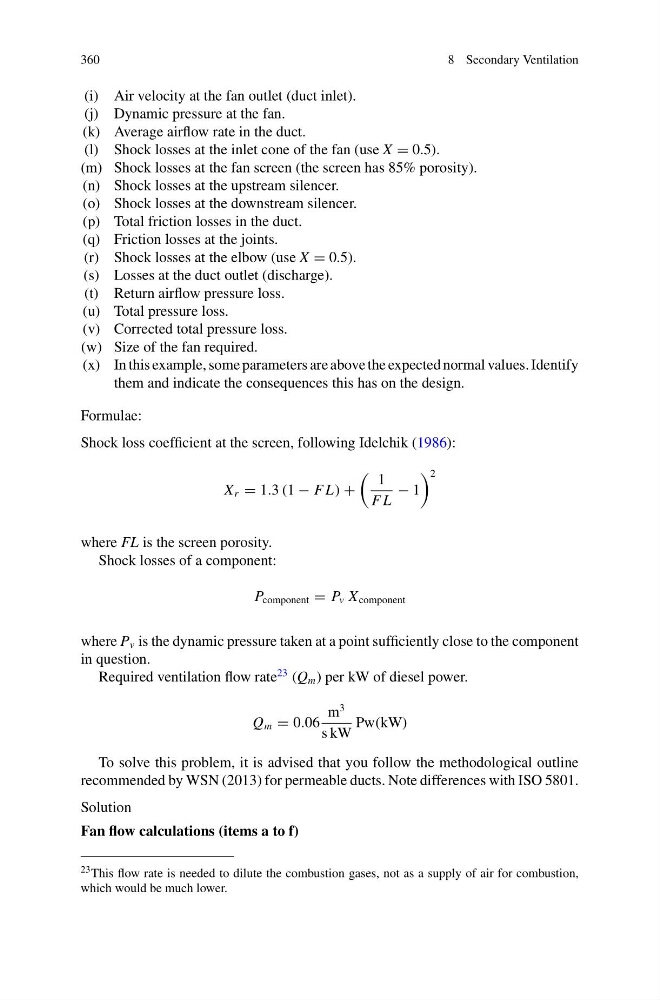
Shock loss coefficient at the screen, following Idelchik (1986):
X r = 1.3 (1 − F L) +
1
F L
− 1
2
where FL is the screen porosity.
Shock losses of a component:
P component = P v X component
where P v is the dynamic pressure taken at a point sufficiently close to the component
in question.
Required ventilation flow rate
23 (Q m ) per kW of diesel power.
Q m = 0.06
m
3
s kW
Pw(kW)
To solve this problem, it is advised that you follow the methodological outline
recommended by WSN (2013) for permeable ducts. Note differences with ISO 5801.
Solution
Fan flow calculations (items a to f)
23 This flow rate is needed to dilute the combustion gases, not as a supply of air for combustion,
which would be much lower.
8 Secondary Ventilation
(i) Air velocity at the fan outlet (duct inlet).
(j) Dynamic pressure at the fan.
(k) Average airflow rate in the duct.
(l) Shock losses at the inlet cone of the fan (use X = 0.5).
(m) Shock losses at the fan screen (the screen has 85% porosity).
(n) Shock losses at the upstream silencer.
(o) Shock losses at the downstream silencer.
(p) Total friction losses in the duct.
(q) Friction losses at the joints.
(r) Shock losses at the elbow (use X = 0.5).
(s) Losses at the duct outlet (discharge).
(t) Return airflow pressure loss.
(u) Total pressure loss.
(v) Corrected total pressure loss.
(w) Size of the fan required.
(x) In this example, some parameters are above the expected normal values. Identify
them and indicate the consequences this has on the design.
Formulae:
Shock loss coefficient at the screen, following Idelchik (1986):
X r = 1.3 (1 − F L) +
1
F L
− 1
2
where FL is the screen porosity.
Shock losses of a component:
P component = P v X component
where P v is the dynamic pressure taken at a point sufficiently close to the component
in question.
Required ventilation flow rate
23 (Q m ) per kW of diesel power.
Q m = 0.06
m
3
s kW
Pw(kW)
To solve this problem, it is advised that you follow the methodological outline
recommended by WSN (2013) for permeable ducts. Note differences with ISO 5801.
Solution
Fan flow calculations (items a to f)
23 This flow rate is needed to dilute the combustion gases, not as a supply of air for combustion,
which would be much lower.