

8.2 Types of Secondary Ventilation
287
8.2.2 Exhausting Ventilation
In exhausting ventilation a fan is placed at one of the ends of a duct, extracting air
from inside it and drawing out contaminated air causing clean air to sweep the face.
Its most important features are:
• It provides a permanently clean zone between the entrance to the gallery and the
beginning of the suction duct.
• It does not move contaminants directly through the gallery but confines them to
the duct.
• It does not achieve an efficient sweep of the blasting gases at the face because the
air that enters through the gallery does so across the whole available cross section,
which decreases its speed and with it its turbulence. Moreover, air entering the
gallery will not necessarily traverse the face before entering the duct, a factor
which also diminishes the effectiveness of this system.
• Mixed exhaust ventilation scheme is not usually used unless the active face is
being advanced by roadheaders or continuous miners.
• The scheme cannot be used in works with firedamp (e.g. ITC 05.0.03 ap.2 [MITC
2000]).
• Dust is directly evacuated meaning that this system is preferred in dusty
conditions.
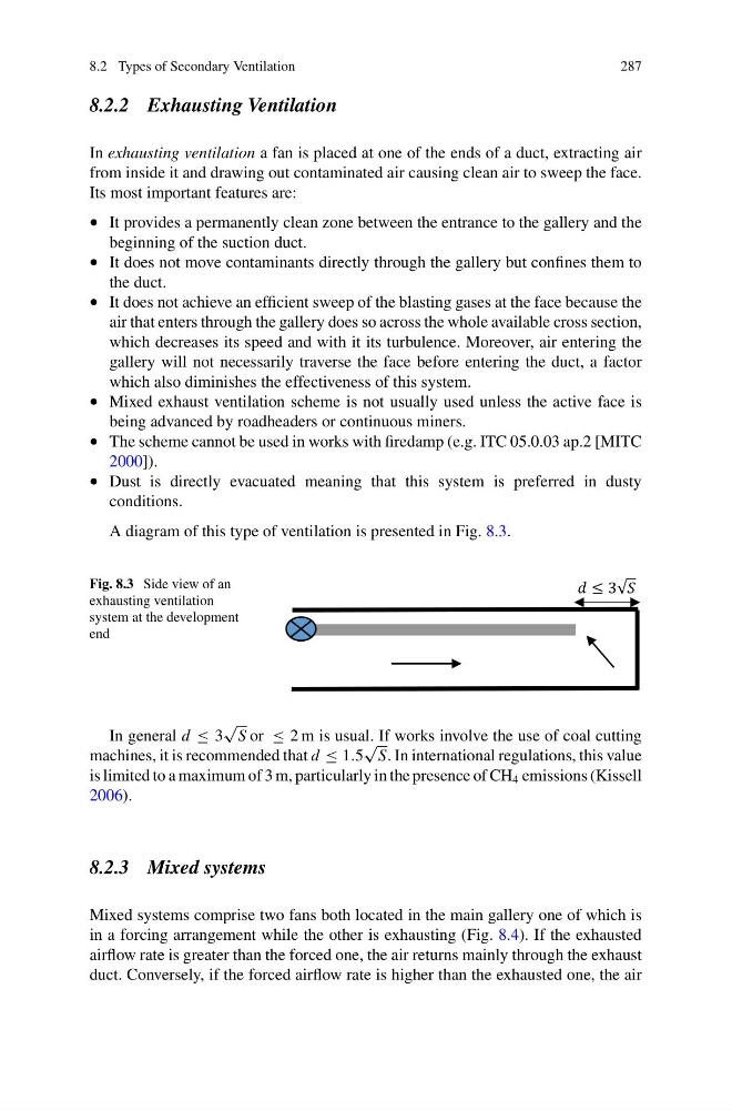
A diagram of this type of ventilation is presented in Fig. 8.3.
Fig. 8.3 Side view of an
exhausting ventilation
system at the development
end
In general d ≤ 3
√
S or ≤ 2 m is usual. If works involve the use of coal cutting
machines, it is recommended that d ≤ 1.5
√
S. In international regulations, this value
is limited to a maximum of 3 m, particularly in the presence of CH 4 emissions (Kissell
2006).
8.2.3 Mixed systems
Mixed systems comprise two fans both located in the main gallery one of which is
in a forcing arrangement while the other is exhausting (Fig. 8.4). If the exhausted
airflow rate is greater than the forced one, the air returns mainly through the exhaust
duct. Conversely, if the forced airflow rate is higher than the exhausted one, the air
287
8.2.2 Exhausting Ventilation
In exhausting ventilation a fan is placed at one of the ends of a duct, extracting air
from inside it and drawing out contaminated air causing clean air to sweep the face.
Its most important features are:
• It provides a permanently clean zone between the entrance to the gallery and the
beginning of the suction duct.
• It does not move contaminants directly through the gallery but confines them to
the duct.
• It does not achieve an efficient sweep of the blasting gases at the face because the
air that enters through the gallery does so across the whole available cross section,
which decreases its speed and with it its turbulence. Moreover, air entering the
gallery will not necessarily traverse the face before entering the duct, a factor
which also diminishes the effectiveness of this system.
• Mixed exhaust ventilation scheme is not usually used unless the active face is
being advanced by roadheaders or continuous miners.
• The scheme cannot be used in works with firedamp (e.g. ITC 05.0.03 ap.2 [MITC
2000]).
• Dust is directly evacuated meaning that this system is preferred in dusty
conditions.
A diagram of this type of ventilation is presented in Fig. 8.3.
Fig. 8.3 Side view of an
exhausting ventilation
system at the development
end
In general d ≤ 3
√
S or ≤ 2 m is usual. If works involve the use of coal cutting
machines, it is recommended that d ≤ 1.5
√
S. In international regulations, this value
is limited to a maximum of 3 m, particularly in the presence of CH 4 emissions (Kissell
2006).
8.2.3 Mixed systems
Mixed systems comprise two fans both located in the main gallery one of which is
in a forcing arrangement while the other is exhausting (Fig. 8.4). If the exhausted
airflow rate is greater than the forced one, the air returns mainly through the exhaust
duct. Conversely, if the forced airflow rate is higher than the exhausted one, the air