

7.7 Calculation of Critical Speed
265
(continued)
Iteration (i)
T f (°C)
V c (m s −1 )
4
179.93
3.28234
5
180.16
3.28178
6
180.19
3.28171
7
180.19
3.28171
8
180.19
3.28171
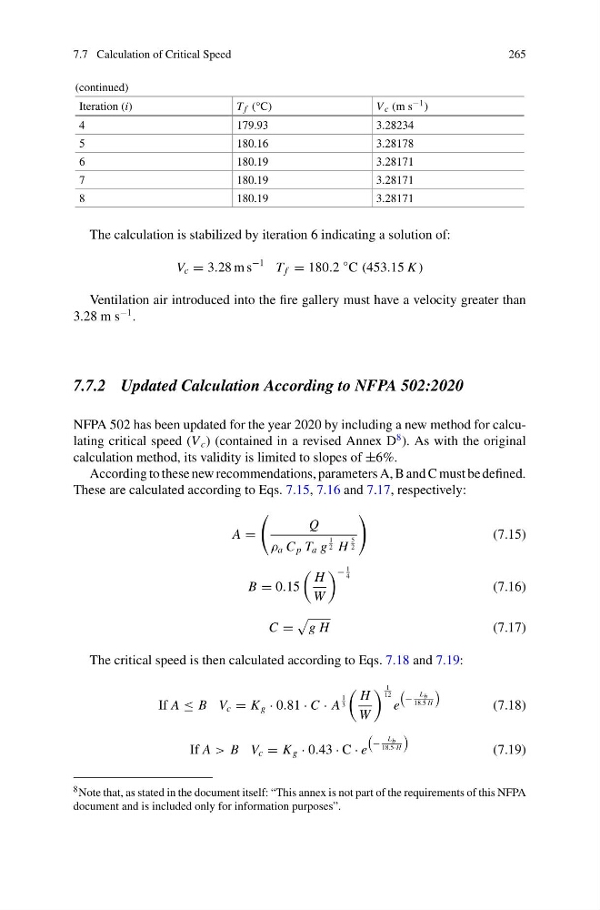
The calculation is stabilized by iteration 6 indicating a solution of:
V c = 3.28 m s
−1 T f = 180.2
◦ C (453.15 K )
Ventilation air introduced into the fire gallery must have a velocity greater than
3.28 m s
−1 .
7.7.2 Updated Calculation According to NFPA 502:2020
NFPA 502 has been updated for the year 2020 by including a new method for calculating critical speed (V c ) (contained in a revised Annex D
8 ). As with the original
calculation method, its validity is limited to slopes of ±6%.
According to these new recommendations, parameters A, B and C must be defined.
These are calculated according to Eqs. 7.15, 7.16 and 7.17, respectively:
A =
Q
ρ a C p T a g
1
2 H
5
2
(7.15)
B = 0.15
H
W
−
1
4
(7.16)
C =
g H
(7.17)
The critical speed is then calculated according to Eqs. 7.18 and 7.19:
If A ≤ B V c = K g · 0.81 · C · A
1
3
H
W
1
12
e
−
L b
18.5 H
(7.18)
If A > B V c = K g · 0.43 · C · e
−
L b
18.5·H
(7.19)
8 Note that, as stated in the document itself: “This annex is not part of the requirements of this NFPA
document and is included only for information purposes”.
265
(continued)
Iteration (i)
T f (°C)
V c (m s −1 )
4
179.93
3.28234
5
180.16
3.28178
6
180.19
3.28171
7
180.19
3.28171
8
180.19
3.28171
The calculation is stabilized by iteration 6 indicating a solution of:
V c = 3.28 m s
−1 T f = 180.2
◦ C (453.15 K )
Ventilation air introduced into the fire gallery must have a velocity greater than
3.28 m s
−1 .
7.7.2 Updated Calculation According to NFPA 502:2020
NFPA 502 has been updated for the year 2020 by including a new method for calculating critical speed (V c ) (contained in a revised Annex D
8 ). As with the original
calculation method, its validity is limited to slopes of ±6%.
According to these new recommendations, parameters A, B and C must be defined.
These are calculated according to Eqs. 7.15, 7.16 and 7.17, respectively:
A =
Q
ρ a C p T a g
1
2 H
5
2
(7.15)
B = 0.15
H
W
−
1
4
(7.16)
C =
g H
(7.17)
The critical speed is then calculated according to Eqs. 7.18 and 7.19:
If A ≤ B V c = K g · 0.81 · C · A
1
3
H
W
1
12
e
−
L b
18.5 H
(7.18)
If A > B V c = K g · 0.43 · C · e
−
L b
18.5·H
(7.19)
8 Note that, as stated in the document itself: “This annex is not part of the requirements of this NFPA
document and is included only for information purposes”.