

178
5 Main Ventilation
(continued)
Triangle
T i
(°C)
h i
(m)
Centroid coordinates T i-1 · h i −T i · h i-1
Area of the
triangle
T cg
h cg
15
0
0
16
175
2625
5
0
12.00
58.33
−875
875
2
5
0
–
16
175
875
6
50
−250
5
0
9.00
75.00
−250
187.5
3
6
50
–
16
175
250
10
175
1050
6
50
10.67
133.33
−550
375
Weighted mean
values
11.26
80.07
Total area
1437.5
5.3.4 Measuring Natural Ventilation
Method of the Ventilation Door
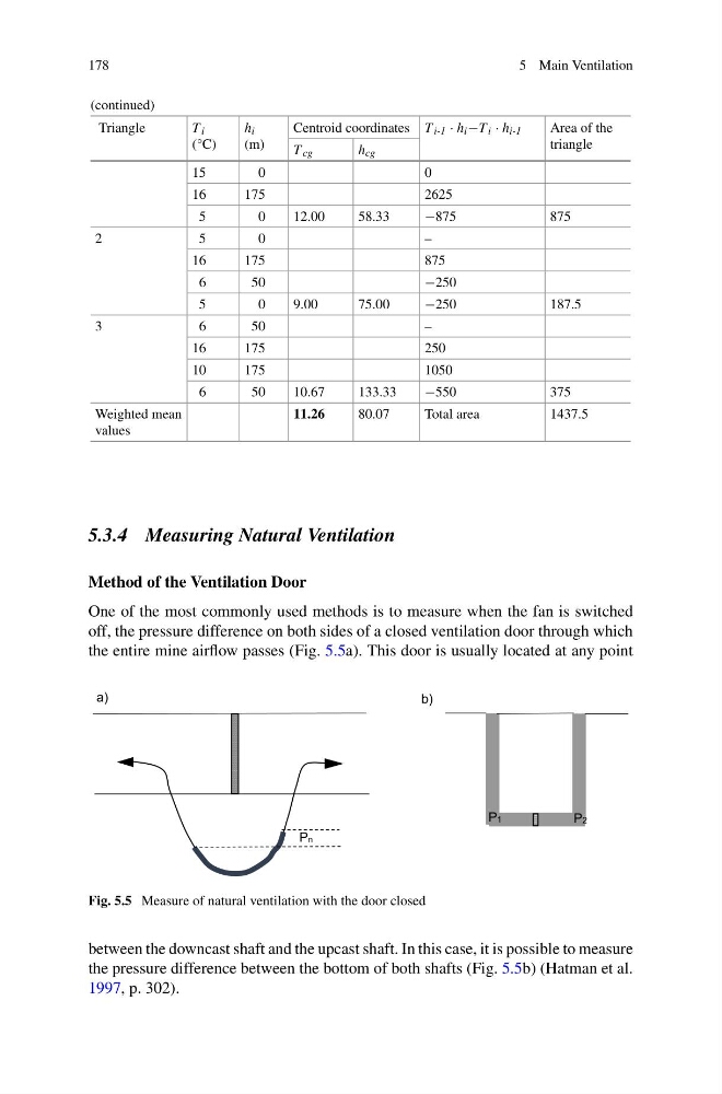
One of the most commonly used methods is to measure when the fan is switched
off, the pressure difference on both sides of a closed ventilation door through which
the entire mine airflow passes (Fig. 5.5a). This door is usually located at any point
Pn
P1
P2
a)
b)
Fig. 5.5 Measure of natural ventilation with the door closed
between the downcast shaft and the upcast shaft. In this case, it is possible to measure
the pressure difference between the bottom of both shafts (Fig. 5.5b) (Hatman et al.
1997, p. 302).
5 Main Ventilation
(continued)
Triangle
T i
(°C)
h i
(m)
Centroid coordinates T i-1 · h i −T i · h i-1
Area of the
triangle
T cg
h cg
15
0
0
16
175
2625
5
0
12.00
58.33
−875
875
2
5
0
–
16
175
875
6
50
−250
5
0
9.00
75.00
−250
187.5
3
6
50
–
16
175
250
10
175
1050
6
50
10.67
133.33
−550
375
Weighted mean
values
11.26
80.07
Total area
1437.5
5.3.4 Measuring Natural Ventilation
Method of the Ventilation Door
One of the most commonly used methods is to measure when the fan is switched
off, the pressure difference on both sides of a closed ventilation door through which
the entire mine airflow passes (Fig. 5.5a). This door is usually located at any point
Pn
P1
P2
a)
b)
Fig. 5.5 Measure of natural ventilation with the door closed
between the downcast shaft and the upcast shaft. In this case, it is possible to measure
the pressure difference between the bottom of both shafts (Fig. 5.5b) (Hatman et al.
1997, p. 302).