

4.3 Concept of Resistance of an Airway
95
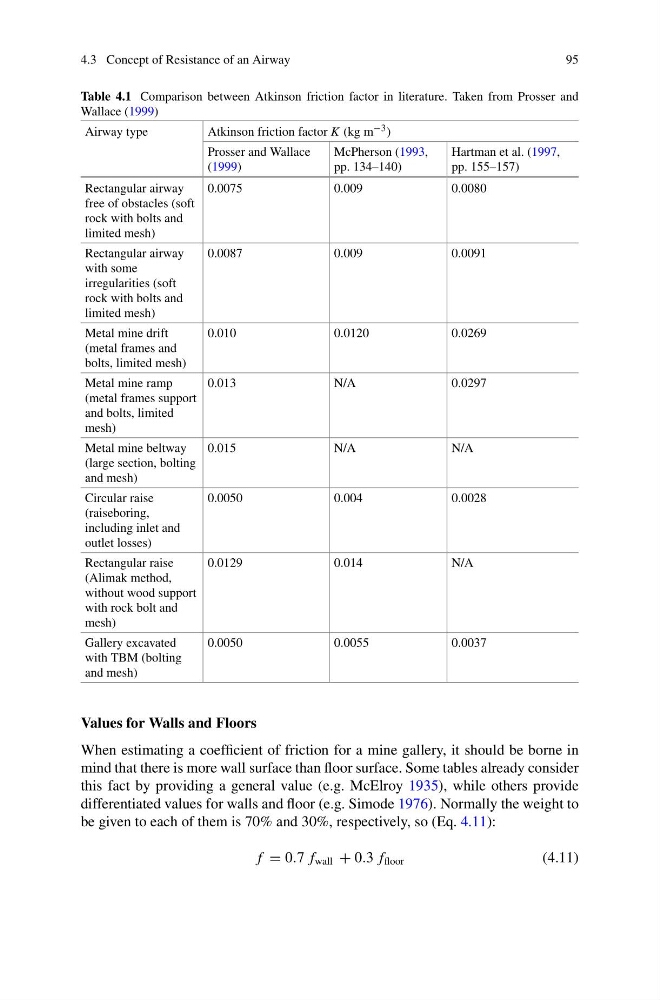
Table 4.1 Comparison between Atkinson friction factor in literature. Taken from Prosser and
Wallace (1999)
Airway type
Atkinson friction factor K (kg m −3 )
Prosser and Wallace
(1999)
McPherson (1993,
pp. 134–140)
Hartman et al. (1997,
pp. 155–157)
Rectangular airway
free of obstacles (soft
rock with bolts and
limited mesh)
0.0075
0.009
0.0080
Rectangular airway
with some
irregularities (soft
rock with bolts and
limited mesh)
0.0087
0.009
0.0091
Metal mine drift
(metal frames and
bolts, limited mesh)
0.010
0.0120
0.0269
Metal mine ramp
(metal frames support
and bolts, limited
mesh)
0.013
N/A
0.0297
Metal mine beltway
(large section, bolting
and mesh)
0.015
N/A
N/A
Circular raise
(raiseboring,
including inlet and
outlet losses)
0.0050
0.004
0.0028
Rectangular raise
(Alimak method,
without wood support
with rock bolt and
mesh)
0.0129
0.014
N/A
Gallery excavated
with TBM (bolting
and mesh)
0.0050
0.0055
0.0037
Values for Walls and Floors
When estimating a coefficient of friction for a mine gallery, it should be borne in
mind that there is more wall surface than floor surface. Some tables already consider
this fact by providing a general value (e.g. McElroy 1935), while others provide
differentiated values for walls and floor (e.g. Simode 1976). Normally the weight to
be given to each of them is 70% and 30%, respectively, so (Eq. 4.11):
f = 0.7 f wall + 0.3 f floor
(4.11)
95
Table 4.1 Comparison between Atkinson friction factor in literature. Taken from Prosser and
Wallace (1999)
Airway type
Atkinson friction factor K (kg m −3 )
Prosser and Wallace
(1999)
McPherson (1993,
pp. 134–140)
Hartman et al. (1997,
pp. 155–157)
Rectangular airway
free of obstacles (soft
rock with bolts and
limited mesh)
0.0075
0.009
0.0080
Rectangular airway
with some
irregularities (soft
rock with bolts and
limited mesh)
0.0087
0.009
0.0091
Metal mine drift
(metal frames and
bolts, limited mesh)
0.010
0.0120
0.0269
Metal mine ramp
(metal frames support
and bolts, limited
mesh)
0.013
N/A
0.0297
Metal mine beltway
(large section, bolting
and mesh)
0.015
N/A
N/A
Circular raise
(raiseboring,
including inlet and
outlet losses)
0.0050
0.004
0.0028
Rectangular raise
(Alimak method,
without wood support
with rock bolt and
mesh)
0.0129
0.014
N/A
Gallery excavated
with TBM (bolting
and mesh)
0.0050
0.0055
0.0037
Values for Walls and Floors
When estimating a coefficient of friction for a mine gallery, it should be borne in
mind that there is more wall surface than floor surface. Some tables already consider
this fact by providing a general value (e.g. McElroy 1935), while others provide
differentiated values for walls and floor (e.g. Simode 1976). Normally the weight to
be given to each of them is 70% and 30%, respectively, so (Eq. 4.11):
f = 0.7 f wall + 0.3 f floor
(4.11)