

62
2 Basic Components
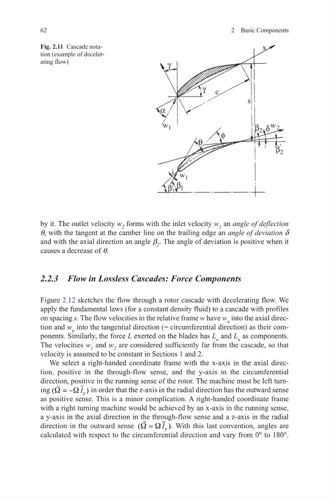
by it. The outlet velocity w 2 forms with the inlet velocity w 1 an angle of deflection
q, with the tangent at the camber line on the trailing edge an angle of deviation d
and with the axial direction an angle β 2 . The angle of deviation is positive when it
causes a decrease of q.
2.2.3 Flow in Lossless Cascades: Force Components
Figure 2.12 sketches the flow through a rotor cascade with decelerating flow. We
apply the fundamental laws (for a constant density fluid) to a cascade with profiles
on spacing s. The flow velocities in the relative frame w have w a into the axial direction and w u into the tangential direction (= circumferential direction) as their components. Similarly, the force L exerted on the blades has L a and L u as components.
The velocities w 1 and w 2 are considered sufficiently far from the cascade, so that
velocity is assumed to be constant in Sections 1 and 2.
We select a right-handed coordinate frame with the x-axis in the axial direction, positive in the through-flow sense, and the y-axis in the circumferential
direction, positive in the running sense of the rotor. The machine must be left turning (
)
x
1
W
W
= −
in order that the z-axis in the radial direction has the outward sense
as positive sense. This is a minor complication. A right-handed coordinate frame
with a right turning machine would be achieved by an x-axis in the running sense,
a y-axis in the axial direction in the through-flow sense and a z-axis in the radial
direction in the outward sense (
)
y
1
W W
=
. With this last convention, angles are
calculated with respect to the circumferential direction and vary from 0° to 180°.
Fig. 2.11 Cascade notation (example of decelerating flow)
2 Basic Components
by it. The outlet velocity w 2 forms with the inlet velocity w 1 an angle of deflection
q, with the tangent at the camber line on the trailing edge an angle of deviation d
and with the axial direction an angle β 2 . The angle of deviation is positive when it
causes a decrease of q.
2.2.3 Flow in Lossless Cascades: Force Components
Figure 2.12 sketches the flow through a rotor cascade with decelerating flow. We
apply the fundamental laws (for a constant density fluid) to a cascade with profiles
on spacing s. The flow velocities in the relative frame w have w a into the axial direction and w u into the tangential direction (= circumferential direction) as their components. Similarly, the force L exerted on the blades has L a and L u as components.
The velocities w 1 and w 2 are considered sufficiently far from the cascade, so that
velocity is assumed to be constant in Sections 1 and 2.
We select a right-handed coordinate frame with the x-axis in the axial direction, positive in the through-flow sense, and the y-axis in the circumferential
direction, positive in the running sense of the rotor. The machine must be left turning (
)
x
1
W
W
= −
in order that the z-axis in the radial direction has the outward sense
as positive sense. This is a minor complication. A right-handed coordinate frame
with a right turning machine would be achieved by an x-axis in the running sense,
a y-axis in the axial direction in the through-flow sense and a z-axis in the radial
direction in the outward sense (
)
y
1
W W
=
. With this last convention, angles are
calculated with respect to the circumferential direction and vary from 0° to 180°.
Fig. 2.11 Cascade notation (example of decelerating flow)