

48
2 Basic Components
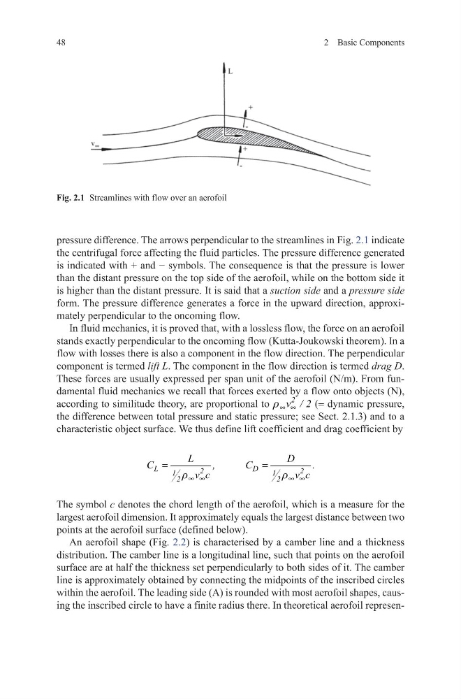
pressure difference. The arrows perpendicular to the streamlines in Fig. 2.1 indicate
the centrifugal force affecting the fluid particles. The pressure difference generated
is indicated with + and − symbols. The consequence is that the pressure is lower
than the distant pressure on the top side of the aerofoil, while on the bottom side it
is higher than the distant pressure. It is said that a suction side and a pressure side
form. The pressure difference generates a force in the upward direction, approximately perpendicular to the oncoming flow.
In fluid mechanics, it is proved that, with a lossless flow, the force on an aerofoil
stands exactly perpendicular to the oncoming flow (Kutta-Joukowski theorem). In a
flow with losses there is also a component in the flow direction. The perpendicular
component is termed lift L. The component in the flow direction is termed drag D.
These forces are usually expressed per span unit of the aerofoil (N/m). From fundamental fluid mechanics we recall that forces exerted by a flow onto objects (N),
according to similitude theory, are proportional to
2
v / 2
r ∞ ∞
(= dynamic pressure,
the difference between total pressure and static pressure; see Sect. 2.1.3) and to a
characteristic object surface. We thus define lift coefficient and drag coefficient by
The symbol c denotes the chord length of the aerofoil, which is a measure for the
largest aerofoil dimension. It approximately equals the largest distance between two
points at the aerofoil surface (defined below).
An aerofoil shape (Fig. 2.2) is characterised by a camber line and a thickness
distribution. The camber line is a longitudinal line, such that points on the aerofoil
surface are at half the thickness set perpendicularly to both sides of it. The camber
line is approximately obtained by connecting the midpoints of the inscribed circles
within the aerofoil. The leading side (A) is rounded with most aerofoil shapes, causing the inscribed circle to have a finite radius there. In theoretical aerofoil represenL
D
2
2
1
1
2
2
L
D
C
,
C
.
v c
v c
r
r
∞ ∞
∞ ∞
=
=
Fig. 2.1 Streamlines with flow over an aerofoil
2 Basic Components
pressure difference. The arrows perpendicular to the streamlines in Fig. 2.1 indicate
the centrifugal force affecting the fluid particles. The pressure difference generated
is indicated with + and − symbols. The consequence is that the pressure is lower
than the distant pressure on the top side of the aerofoil, while on the bottom side it
is higher than the distant pressure. It is said that a suction side and a pressure side
form. The pressure difference generates a force in the upward direction, approximately perpendicular to the oncoming flow.
In fluid mechanics, it is proved that, with a lossless flow, the force on an aerofoil
stands exactly perpendicular to the oncoming flow (Kutta-Joukowski theorem). In a
flow with losses there is also a component in the flow direction. The perpendicular
component is termed lift L. The component in the flow direction is termed drag D.
These forces are usually expressed per span unit of the aerofoil (N/m). From fundamental fluid mechanics we recall that forces exerted by a flow onto objects (N),
according to similitude theory, are proportional to
2
v / 2
r ∞ ∞
(= dynamic pressure,
the difference between total pressure and static pressure; see Sect. 2.1.3) and to a
characteristic object surface. We thus define lift coefficient and drag coefficient by
The symbol c denotes the chord length of the aerofoil, which is a measure for the
largest aerofoil dimension. It approximately equals the largest distance between two
points at the aerofoil surface (defined below).
An aerofoil shape (Fig. 2.2) is characterised by a camber line and a thickness
distribution. The camber line is a longitudinal line, such that points on the aerofoil
surface are at half the thickness set perpendicularly to both sides of it. The camber
line is approximately obtained by connecting the midpoints of the inscribed circles
within the aerofoil. The leading side (A) is rounded with most aerofoil shapes, causing the inscribed circle to have a finite radius there. In theoretical aerofoil represenL
D
2
2
1
1
2
2
L
D
C
,
C
.
v c
v c
r
r
∞ ∞
∞ ∞
=
=
Fig. 2.1 Streamlines with flow over an aerofoil