

553
15.2 Radial Turbines
Two kinematic parameters are thus determined: R and ψ (or λ). The third parameter,
the flow coefficient ϕ, follows from efficiency optimisation.
Losses are very low within the volute and the vane ring. Losses within the
rotor are significantly higher, due to the separation bubble and the segregation
as a consequence of the Coriolis force and the centrifugal force associated to the
flow turning in the meridional plane. A significant loss further occurs due to the
clearance between the open rotor and the casing and to the high friction velocity on
the casing (absolute velocity). A closed rotor would be more advantageous regarding these aspects. The losses within the diffuser are also very high. Optimisation
thus means, in principle, minimising the sum of rotor and diffuser losses. This optimisation cannot be achieved with simple means, as the result depends strongly on
the loss coefficient values, which cannot be expressed by simple correlations. The
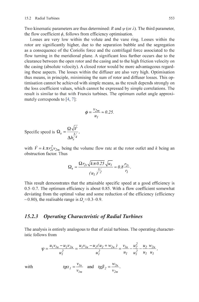
result is similar to that with Francis turbines. The optimum outlet angle approximately corresponds to [4, 7]:
Specific speed is s
3 4
s
V ,
h
W
W
D
=
with
2
2t 2m
V k r v
p
=
being the volume flow rate at the rotor outlet and k being an
obstruction factor. Thus
This result demonstrates that the attainable specific speed at a good efficiency is
0.5–0.7. The optimum efficiency is about 0.85. With a flow coefficient somewhat
deviating from the optimal value and some reduction of the efficiency (efficiency
~ 0.80), the realisable range is Ω s ≈ 0.3–0.9.
15.2.3 Operating Characteristic of Radial Turbines
The analysis is entirely analogous to that of axial turbines. The operating characteristic follows from
2m
1
v
0.25.
u
f =
≈
2t
1
2t
s
3
1
2
1
r k 0.25 u
r
0.8 .
r
( u )
W
p
W ≈
≈
2
1 1u
2 2u
1 1u
2 2
2u
1u
2u
2
2
2
2
2
1
1
1
1
1
1
u v
u v
u v
u ( u w ) v
w
u
u
,
u
u u
u
u
u
y
−
−
+
=
=
=
−
−
with
and
.
1u
2u
1
2
1m
2m
v
w
tg
tg
v
v
a
b
=
=
15.2 Radial Turbines
Two kinematic parameters are thus determined: R and ψ (or λ). The third parameter,
the flow coefficient ϕ, follows from efficiency optimisation.
Losses are very low within the volute and the vane ring. Losses within the
rotor are significantly higher, due to the separation bubble and the segregation
as a consequence of the Coriolis force and the centrifugal force associated to the
flow turning in the meridional plane. A significant loss further occurs due to the
clearance between the open rotor and the casing and to the high friction velocity on
the casing (absolute velocity). A closed rotor would be more advantageous regarding these aspects. The losses within the diffuser are also very high. Optimisation
thus means, in principle, minimising the sum of rotor and diffuser losses. This optimisation cannot be achieved with simple means, as the result depends strongly on
the loss coefficient values, which cannot be expressed by simple correlations. The
result is similar to that with Francis turbines. The optimum outlet angle approximately corresponds to [4, 7]:
Specific speed is s
3 4
s
V ,
h
W
W
D
=
with
2
2t 2m
V k r v
p
=
being the volume flow rate at the rotor outlet and k being an
obstruction factor. Thus
This result demonstrates that the attainable specific speed at a good efficiency is
0.5–0.7. The optimum efficiency is about 0.85. With a flow coefficient somewhat
deviating from the optimal value and some reduction of the efficiency (efficiency
~ 0.80), the realisable range is Ω s ≈ 0.3–0.9.
15.2.3 Operating Characteristic of Radial Turbines
The analysis is entirely analogous to that of axial turbines. The operating characteristic follows from
2m
1
v
0.25.
u
f =
≈
2t
1
2t
s
3
1
2
1
r k 0.25 u
r
0.8 .
r
( u )
W
p
W ≈
≈
2
1 1u
2 2u
1 1u
2 2
2u
1u
2u
2
2
2
2
2
1
1
1
1
1
1
u v
u v
u v
u ( u w ) v
w
u
u
,
u
u u
u
u
u
y
−
−
+
=
=
=
−
−
with
and
.
1u
2u
1
2
1m
2m
v
w
tg
tg
v
v
a
b
=
=