

524
14 Radial Compressors
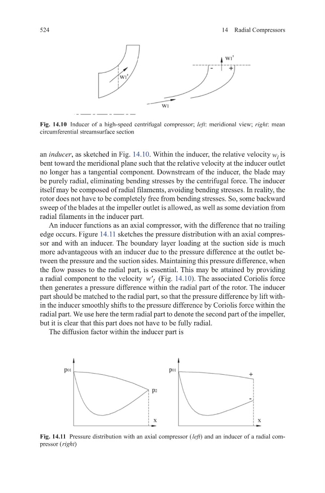
an inducer, as sketched in Fig. 14.10. Within the inducer, the relative velocity w 1 is
bent toward the meridional plane such that the relative velocity at the inducer outlet
no longer has a tangential component. Downstream of the inducer, the blade may
be purely radial, eliminating bending stresses by the centrifugal force. The inducer
itself may be composed of radial filaments, avoiding bending stresses. In reality, the
rotor does not have to be completely free from bending stresses. So, some backward
sweep of the blades at the impeller outlet is allowed, as well as some deviation from
radial filaments in the inducer part.
An inducer functions as an axial compressor, with the difference that no trailing
edge occurs. Figure 14.11 sketches the pressure distribution with an axial compressor and with an inducer. The boundary layer loading at the suction side is much
more advantageous with an inducer due to the pressure difference at the outlet between the pressure and the suction sides. Maintaining this pressure difference, when
the flow passes to the radial part, is essential. This may be attained by providing
a radial component to the velocity 1
w' (Fig. 14.10). The associated Coriolis force
then generates a pressure difference within the radial part of the rotor. The inducer
part should be matched to the radial part, so that the pressure difference by lift within the inducer smoothly shifts to the pressure difference by Coriolis force within the
radial part. We use here the term radial part to denote the second part of the impeller,
but it is clear that this part does not have to be fully radial.
The diffusion factor within the inducer part is
Fig. 14.11 Pressure distribution with an axial compressor ( left) and an inducer of a radial compressor ( right)
Fig. 14.10 Inducer of a high-speed centrifugal compressor; left: meridional view; right: mean
circumferential streamsurface section
14 Radial Compressors
an inducer, as sketched in Fig. 14.10. Within the inducer, the relative velocity w 1 is
bent toward the meridional plane such that the relative velocity at the inducer outlet
no longer has a tangential component. Downstream of the inducer, the blade may
be purely radial, eliminating bending stresses by the centrifugal force. The inducer
itself may be composed of radial filaments, avoiding bending stresses. In reality, the
rotor does not have to be completely free from bending stresses. So, some backward
sweep of the blades at the impeller outlet is allowed, as well as some deviation from
radial filaments in the inducer part.
An inducer functions as an axial compressor, with the difference that no trailing
edge occurs. Figure 14.11 sketches the pressure distribution with an axial compressor and with an inducer. The boundary layer loading at the suction side is much
more advantageous with an inducer due to the pressure difference at the outlet between the pressure and the suction sides. Maintaining this pressure difference, when
the flow passes to the radial part, is essential. This may be attained by providing
a radial component to the velocity 1
w' (Fig. 14.10). The associated Coriolis force
then generates a pressure difference within the radial part of the rotor. The inducer
part should be matched to the radial part, so that the pressure difference by lift within the inducer smoothly shifts to the pressure difference by Coriolis force within the
radial part. We use here the term radial part to denote the second part of the impeller,
but it is clear that this part does not have to be fully radial.
The diffusion factor within the inducer part is
Fig. 14.11 Pressure distribution with an axial compressor ( left) and an inducer of a radial compressor ( right)
Fig. 14.10 Inducer of a high-speed centrifugal compressor; left: meridional view; right: mean
circumferential streamsurface section