

522
14 Radial Compressors
rotor outlet, the second term is negative at the rotor outlet. The equation may also be
derived directly, albeit with the necessity of some approximations, from a moment
of momentum balance on a streamtube with infinitesimal radial length, spanning
a blade passage (see Exercise 14.7.1). Based on (14.6), we may write at the rotor
outlet:
and
(14.7)
where w 2 is the average relative flow velocity at the rotor outlet and f R is a factor
smaller than unity, expressing the influence of the curvature of the streamlines in
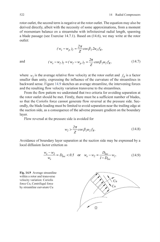
backward sense. Figure 14.9 sketches an average streamline, the intervening forces
and the resulting flow velocity variation transverse to the streamlines.
From the flow pattern we understand that two criteria for avoiding separation at
the rotor outlet should be met. Firstly, there must be a sufficient number of blades,
so that the Coriolis force cannot generate flow reversal at the pressure side. Secondly, the blade loading must be limited to avoid separation near the trailing edge at
the suction side, as a consequence of the adverse pressure gradient on the boundary
layer.
Flow reversal at the pressure side is avoided for
(14.8)
Avoidance of boundary layer separation at the suction side may be expressed by a
local diffusion factor criterion as
(14.9)
p
b
−
=
s
p 2
2
2 R
2
( w w )
cos 2u f ,
Z
s
2 2
2
p 2
2 2 R
2
( w w ) ( w w )
cos u f ,
Z
p
b
−
=
−
=
p
b
>
2
2 2 R
2
w
cos u f .
Z
or
−
=
<
−
= −
s
2
loc
loc
s
2
2
s
loc
w w
D
D
0.5
w w
w .
w
1 D
Fig. 14.9 Average streamline
within a rotor and transverse
velocity variation: Coriolis
force Co, Centrifugal force
by streamline curvature Cu
14 Radial Compressors
rotor outlet, the second term is negative at the rotor outlet. The equation may also be
derived directly, albeit with the necessity of some approximations, from a moment
of momentum balance on a streamtube with infinitesimal radial length, spanning
a blade passage (see Exercise 14.7.1). Based on (14.6), we may write at the rotor
outlet:
and
(14.7)
where w 2 is the average relative flow velocity at the rotor outlet and f R is a factor
smaller than unity, expressing the influence of the curvature of the streamlines in
backward sense. Figure 14.9 sketches an average streamline, the intervening forces
and the resulting flow velocity variation transverse to the streamlines.
From the flow pattern we understand that two criteria for avoiding separation at
the rotor outlet should be met. Firstly, there must be a sufficient number of blades,
so that the Coriolis force cannot generate flow reversal at the pressure side. Secondly, the blade loading must be limited to avoid separation near the trailing edge at
the suction side, as a consequence of the adverse pressure gradient on the boundary
layer.
Flow reversal at the pressure side is avoided for
(14.8)
Avoidance of boundary layer separation at the suction side may be expressed by a
local diffusion factor criterion as
(14.9)
p
b
−
=
s
p 2
2
2 R
2
( w w )
cos 2u f ,
Z
s
2 2
2
p 2
2 2 R
2
( w w ) ( w w )
cos u f ,
Z
p
b
−
=
−
=
p
b
>
2
2 2 R
2
w
cos u f .
Z
or
−
=
<
−
= −
s
2
loc
loc
s
2
2
s
loc
w w
D
D
0.5
w w
w .
w
1 D
Fig. 14.9 Average streamline
within a rotor and transverse
velocity variation: Coriolis
force Co, Centrifugal force
by streamline curvature Cu