

484
13 Axial Compressors
We calculate the velocity triangles on the radii
m
r / r
o
= 1.20 (outer radius of the
flow annulus) and r r
i
m
/ = 0.75 (inner radius of the flow annulus). With this choice,
the through-flow areas above and under the average radius are equal. The radius
variation is rather great, typical for first stages in a real compressor. With a fan
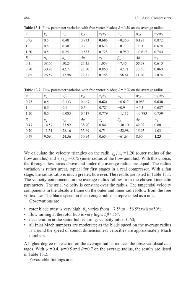
stage, the radius ratio is much greater, however. The results are listed in Table 13.1.
The velocity components on the average radius follow from the chosen kinematic
parameters. The axial velocity is constant over the radius. The tangential velocity
components in the absolute frame on the outer and inner radii follow from the free
vortex law. The blade speed on the average radius is represented as a unit.
Observations are:
• rotor blade twist is very high: β m varies fr om − 7.5° to − 56.5°: twist ≈ 50°;
• flow turning at the rotor hub is very high: Δβ ≈ 55°;
• deceleration at the stator hub is strong: velocity ratio ≈ 0.60;
• all inlet Mach numbers are moderate; as the blade speed on the average radius
is around the speed of sound, dimensionless velocities are approximately Mach
numbers.
A higher degree of reaction on the average radius reduces the observed disadvantages. With ψ = 0.4, ϕ = 0.5 and R = 0.7 on the average radius, the results are listed
in Table 13.2.
Favourable findings are:
Table 13.1 Flow parameter variation with free vortex blades; R = 0.50 on the average radius
u
v a
v u1
v u2
v 1 /v 2
w u1
w u2
w 2 /w 1
0.75
0.5
0.40
0.933
0.605
− 0.350
0.183
0.872
1
0.5
0.30
0.7
0.678
− 0.7
− 0.3
0.678
1.20
0.5
0.25
0.583
0.728
− 0.950
− 0.617
0.740
R
α 1
α m
Δα
v 2
β m
Δβ
w 1
0.11
38.66
50.24
23.15
1.058
− 7.45
55.09
0.610
0.50
30.96
42.71
23.50
0.860
− 42.71
23.50
0.860
0.65
26.57
37.98
22.81
0.768
− 56.61
11.26
1.074
Table 13.2 Flow parameter variation with free vortex blades; R = 0.70 on the average radius
u
v a
v u1
v u2
v 1 /v 2
w u1
w u2
w 2 /w 1
0.75
0.5
0.133
0.667
0.621
− 0.617
0.083
0.638
1
0.5
0.1
0.5
0.721
− 0.9
− 0.5
0.687
1.20
0.5
0.083
0.417
0.779
− 1.117
− 0.783
0.759
R
α 1
α m
Δα
v 2
β m
Δβ
w 1
0.47
14.57
33.92
38.70
0.84
− 30.10
42.02
0.80
0.70
11.31
28.16
33.69
0.71
− 52.98
15.95
1.03
0.79
9.09
24.56
30.94
0.65
− 61.64
8.60
1.23
13 Axial Compressors
We calculate the velocity triangles on the radii
m
r / r
o
= 1.20 (outer radius of the
flow annulus) and r r
i
m
/ = 0.75 (inner radius of the flow annulus). With this choice,
the through-flow areas above and under the average radius are equal. The radius
variation is rather great, typical for first stages in a real compressor. With a fan
stage, the radius ratio is much greater, however. The results are listed in Table 13.1.
The velocity components on the average radius follow from the chosen kinematic
parameters. The axial velocity is constant over the radius. The tangential velocity
components in the absolute frame on the outer and inner radii follow from the free
vortex law. The blade speed on the average radius is represented as a unit.
Observations are:
• rotor blade twist is very high: β m varies fr om − 7.5° to − 56.5°: twist ≈ 50°;
• flow turning at the rotor hub is very high: Δβ ≈ 55°;
• deceleration at the stator hub is strong: velocity ratio ≈ 0.60;
• all inlet Mach numbers are moderate; as the blade speed on the average radius
is around the speed of sound, dimensionless velocities are approximately Mach
numbers.
A higher degree of reaction on the average radius reduces the observed disadvantages. With ψ = 0.4, ϕ = 0.5 and R = 0.7 on the average radius, the results are listed
in Table 13.2.
Favourable findings are:
Table 13.1 Flow parameter variation with free vortex blades; R = 0.50 on the average radius
u
v a
v u1
v u2
v 1 /v 2
w u1
w u2
w 2 /w 1
0.75
0.5
0.40
0.933
0.605
− 0.350
0.183
0.872
1
0.5
0.30
0.7
0.678
− 0.7
− 0.3
0.678
1.20
0.5
0.25
0.583
0.728
− 0.950
− 0.617
0.740
R
α 1
α m
Δα
v 2
β m
Δβ
w 1
0.11
38.66
50.24
23.15
1.058
− 7.45
55.09
0.610
0.50
30.96
42.71
23.50
0.860
− 42.71
23.50
0.860
0.65
26.57
37.98
22.81
0.768
− 56.61
11.26
1.074
Table 13.2 Flow parameter variation with free vortex blades; R = 0.70 on the average radius
u
v a
v u1
v u2
v 1 /v 2
w u1
w u2
w 2 /w 1
0.75
0.5
0.133
0.667
0.621
− 0.617
0.083
0.638
1
0.5
0.1
0.5
0.721
− 0.9
− 0.5
0.687
1.20
0.5
0.083
0.417
0.779
− 1.117
− 0.783
0.759
R
α 1
α m
Δα
v 2
β m
Δβ
w 1
0.47
14.57
33.92
38.70
0.84
− 30.10
42.02
0.80
0.70
11.31
28.16
33.69
0.71
− 52.98
15.95
1.03
0.79
9.09
24.56
30.94
0.65
− 61.64
8.60
1.23