

439
12.4 Performance of the Gas Generator and the Single-Jet Engine
12.4.1 Analysis with Loss-Free Components
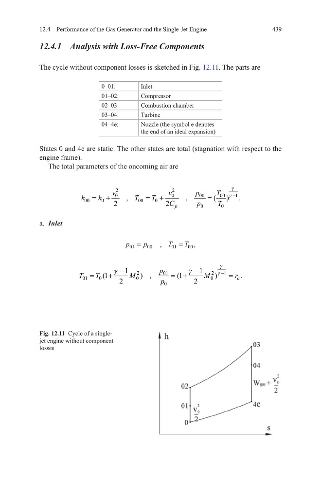
The cycle without component losses is sketched in Fig. 12.11. The parts are
0–01:
Inlet
01–02:
Compressor
02–03:
Combustion chamber
03–04:
Turbine
04–4e:
Nozzle (the symbol e denotes
the end of an ideal expansion)
States 0 and 4e are static. The other states are total (stagnation with respect to the
engine frame).
The total parameters of the oncoming air are
a. Inlet
2
2
1
0
0
00
00
00
0
00
0
0
0
,
,
( ) .
2
2 p
v
v
p
T
h
h
T
T
C
p
T
g
g −
= +
= +
=
p
p
T
T
01
00
01
00
= = ,
,
2
21
01
01
0
0
0
0
1
1
(1
) ,
(1
)
.
2
2
a
p
T
T
M
M
r
p
g
g
g
g
−
−
−
=
+
= +
=
Fig. 12.11 Cycle of a singlejet engine without component
losses
12.4 Performance of the Gas Generator and the Single-Jet Engine
12.4.1 Analysis with Loss-Free Components
The cycle without component losses is sketched in Fig. 12.11. The parts are
0–01:
Inlet
01–02:
Compressor
02–03:
Combustion chamber
03–04:
Turbine
04–4e:
Nozzle (the symbol e denotes
the end of an ideal expansion)
States 0 and 4e are static. The other states are total (stagnation with respect to the
engine frame).
The total parameters of the oncoming air are
a. Inlet
2
2
1
0
0
00
00
00
0
00
0
0
0
,
,
( ) .
2
2 p
v
v
p
T
h
h
T
T
C
p
T
g
g −
= +
= +
=
p
p
T
T
01
00
01
00
= = ,
,
2
21
01
01
0
0
0
0
1
1
(1
) ,
(1
)
.
2
2
a
p
T
T
M
M
r
p
g
g
g
g
−
−
−
=
+
= +
=
Fig. 12.11 Cycle of a singlejet engine without component
losses