

17
1.5 Basic Laws for Rotating Duct Parts
the blades is mostly called the rotor disc (in general, the disc is curved), but the
term hub is often used for the complete inner part. The flow is guided by the blade
surfaces. With a closed rotor, the flow is guided by the shroud and the hub as well.
The shroud and hub then constitute the end walls. With a closed rotor, all guiding
surfaces are in the relative frame. With an open type, the end wall at the hub side is
in the relative frame and the end wall at the casing side is in the absolute frame. We
first analyse the closed form.
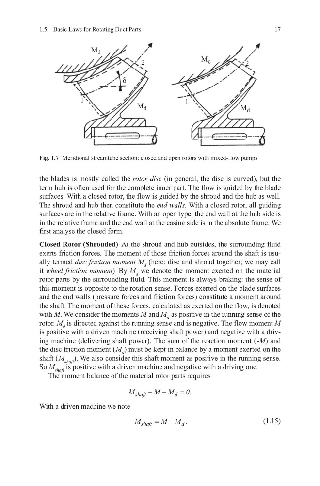
Closed Rotor (Shrouded) At the shroud and hub outsides, the surrounding fluid
exerts friction forces. The moment of those friction forces around the shaft is usually termed disc friction moment M d (here: disc and shroud together; we may call
it wheel friction moment) . By M d we denote the moment exerted on the material
rotor parts by the surrounding fluid. This moment is always braking: the sense of
this moment is opposite to the rotation sense. Forces exerted on the blade surfaces
and the end walls (pressure forces and friction forces) constitute a moment around
the shaft. The moment of these forces, calculated as exerted on the flow, is denoted
with M. We consider the moments M and M d as positive in the running sense of the
rotor. M d is directed against the running sense and is negative. The flow moment M
is positive with a driven machine (receiving shaft power) and negative with a driving machine (delivering shaft power). The sum of the reaction moment ( -M) and
the disc friction moment ( M d ) must be kept in balance by a moment exerted on the
shaft ( M shaft ). We also consider this shaft moment as positive in the running sense.
So M shaft is positive with a driven machine and negative with a driving one.
The moment balance of the material rotor parts requires
With a driven machine we note
(1.15)
M
M M
shaft
d
− +
= 0.
M
M M
shaft
d
= −
.
Fig. 1.7 Meridional streamtube section: closed and open rotors with mixed-flow pumps
1.5 Basic Laws for Rotating Duct Parts
the blades is mostly called the rotor disc (in general, the disc is curved), but the
term hub is often used for the complete inner part. The flow is guided by the blade
surfaces. With a closed rotor, the flow is guided by the shroud and the hub as well.
The shroud and hub then constitute the end walls. With a closed rotor, all guiding
surfaces are in the relative frame. With an open type, the end wall at the hub side is
in the relative frame and the end wall at the casing side is in the absolute frame. We
first analyse the closed form.
Closed Rotor (Shrouded) At the shroud and hub outsides, the surrounding fluid
exerts friction forces. The moment of those friction forces around the shaft is usually termed disc friction moment M d (here: disc and shroud together; we may call
it wheel friction moment) . By M d we denote the moment exerted on the material
rotor parts by the surrounding fluid. This moment is always braking: the sense of
this moment is opposite to the rotation sense. Forces exerted on the blade surfaces
and the end walls (pressure forces and friction forces) constitute a moment around
the shaft. The moment of these forces, calculated as exerted on the flow, is denoted
with M. We consider the moments M and M d as positive in the running sense of the
rotor. M d is directed against the running sense and is negative. The flow moment M
is positive with a driven machine (receiving shaft power) and negative with a driving machine (delivering shaft power). The sum of the reaction moment ( -M) and
the disc friction moment ( M d ) must be kept in balance by a moment exerted on the
shaft ( M shaft ). We also consider this shaft moment as positive in the running sense.
So M shaft is positive with a driven machine and negative with a driving one.
The moment balance of the material rotor parts requires
With a driven machine we note
(1.15)
M
M M
shaft
d
− +
= 0.
M
M M
shaft
d
= −
.
Fig. 1.7 Meridional streamtube section: closed and open rotors with mixed-flow pumps