

9 Hydraulic Turbines
338
9.5 Bulb and Tube Turbines
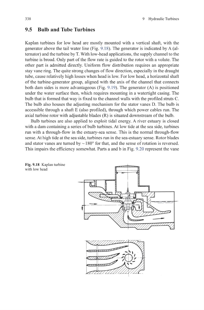
Kaplan turbines for low head are mostly mounted with a vertical shaft, with the
generator above the tail water line (Fig. 9.18). The generator is indicated by A (alternator) and the turbine by T. With low-head applications, the supply channel to the
turbine is broad. Only part of the flow rate is guided to the rotor with a volute. The
other part is admitted directly. Uniform flow distribution requires an appropriate
stay vane ring. The quite strong changes of flow direction, especially in the draught
tube, cause relatively high losses when head is low. For low head, a horizontal shaft
of the turbine-generator group, aligned with the axis of the channel that connects
both dam sides is more advantageous (Fig. 9.19). The generator (A) is positioned
under the water surface then, which requires mounting in a watertight casing. The
bulb that is formed that way is fixed to the channel walls with the profiled struts C.
The bulb also houses the adjusting mechanism for the stator vanes D. The bulb is
accessible through a shaft E (also profiled), through which power cables run. The
axial turbine rotor with adjustable blades (R) is situated downstream of the bulb.
Bulb turbines are also applied to exploit tidal energy. A river estuary is closed
with a dam containing a series of bulb turbines. At low tide at the sea side, turbines
run with a through-flow in the estuary-sea sense. This is the normal through-flow
sense. At high tide at the sea side, turbines run in the sea-estuary sense. Rotor blades
and stator vanes are turned by ~ 180° for that, and the sense of rotation is reversed.
This impairs the efficiency somewhat. Parts a and b in Fig. 9.20 represent the vane
Fig. 9.18 Kaplan turbine
with low head
338
9.5 Bulb and Tube Turbines
Kaplan turbines for low head are mostly mounted with a vertical shaft, with the
generator above the tail water line (Fig. 9.18). The generator is indicated by A (alternator) and the turbine by T. With low-head applications, the supply channel to the
turbine is broad. Only part of the flow rate is guided to the rotor with a volute. The
other part is admitted directly. Uniform flow distribution requires an appropriate
stay vane ring. The quite strong changes of flow direction, especially in the draught
tube, cause relatively high losses when head is low. For low head, a horizontal shaft
of the turbine-generator group, aligned with the axis of the channel that connects
both dam sides is more advantageous (Fig. 9.19). The generator (A) is positioned
under the water surface then, which requires mounting in a watertight casing. The
bulb that is formed that way is fixed to the channel walls with the profiled struts C.
The bulb also houses the adjusting mechanism for the stator vanes D. The bulb is
accessible through a shaft E (also profiled), through which power cables run. The
axial turbine rotor with adjustable blades (R) is situated downstream of the bulb.
Bulb turbines are also applied to exploit tidal energy. A river estuary is closed
with a dam containing a series of bulb turbines. At low tide at the sea side, turbines
run with a through-flow in the estuary-sea sense. This is the normal through-flow
sense. At high tide at the sea side, turbines run in the sea-estuary sense. Rotor blades
and stator vanes are turned by ~ 180° for that, and the sense of rotation is reversed.
This impairs the efficiency somewhat. Parts a and b in Fig. 9.20 represent the vane
Fig. 9.18 Kaplan turbine
with low head