

9.4 Francis and Kaplan Turbines: Reaction Turbines
335
in Table 9.3 establish that the kinetic energy to be recovered in the draught tube
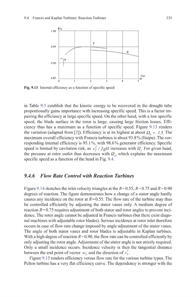
proportionally gains importance with increasing specific speed. This is a factor impairing the efficiency at large specific speed. On the other hand, with a low specific
speed, the blade surface in the rotor is large, causing large friction losses. Efficiency thus has a maximum as a function of specific speed. Figure 9.13 renders
the variation (adapted from [2]). Efficiency is at its highest at about Ω s 1
= . .
5 The
maximum overall efficiency with Francis turbines is about 93.8 % (Itaipu). The corresponding internal efficiency is 95.1 %, with 98.6 % generator efficiency. Specific
speed is limited by cavitation risk, as v
gH
2
2
2
/
increases with Ω s . For given head,
the pressure at rotor outlet thus decreases with Ω s , which explains the maximum
specific speed as a function of the head in Fig. 9.4.
9.4.6 Flow Rate Control with Reaction Turbines
Figure 9.14 sketches the inlet velocity triangles at the R = 0.55, R = 0.75 and R = 0.90
degrees of reaction. The figure demonstrates how a change of a stator angle hardly
causes any incidence on the rotor at R = 0.55. The flow rate of the turbine may thus
be controlled efficiently by adjusting the stator vanes only. A medium degree of
reaction R = 0.75 requires adjustment of both stator and rotor angles to prevent incidence. The rotor angle cannot be adjusted in Francis turbines (but there exist diagonal machines with adjustable rotor blades). Serious incidence at rotor inlet therefore
occurs in case of flow rate change imposed by angle adjustment of the stator vanes.
The angle of both stator vanes and rotor blades is adjustable in Kaplan turbines.
With a high degree of reaction R = 0.90, the flow rate can be controlled efficiently by
only adjusting the rotor angle. Adjustment of the stator angle is not strictly required.
Only a small incidence occurs. Incidence velocity is then the tangential distance
between the end point of vector w 1
−
and the direction of v 1
*
.
Figure 9.15 renders efficiency versus flow rate for the various turbine types. The
Pelton turbine has a very flat efficiency curve. The dependency is stronger with the
Fig. 9.13 Internal efficiency as a function of specific speed
335
in Table 9.3 establish that the kinetic energy to be recovered in the draught tube
proportionally gains importance with increasing specific speed. This is a factor impairing the efficiency at large specific speed. On the other hand, with a low specific
speed, the blade surface in the rotor is large, causing large friction losses. Efficiency thus has a maximum as a function of specific speed. Figure 9.13 renders
the variation (adapted from [2]). Efficiency is at its highest at about Ω s 1
= . .
5 The
maximum overall efficiency with Francis turbines is about 93.8 % (Itaipu). The corresponding internal efficiency is 95.1 %, with 98.6 % generator efficiency. Specific
speed is limited by cavitation risk, as v
gH
2
2
2
/
increases with Ω s . For given head,
the pressure at rotor outlet thus decreases with Ω s , which explains the maximum
specific speed as a function of the head in Fig. 9.4.
9.4.6 Flow Rate Control with Reaction Turbines
Figure 9.14 sketches the inlet velocity triangles at the R = 0.55, R = 0.75 and R = 0.90
degrees of reaction. The figure demonstrates how a change of a stator angle hardly
causes any incidence on the rotor at R = 0.55. The flow rate of the turbine may thus
be controlled efficiently by adjusting the stator vanes only. A medium degree of
reaction R = 0.75 requires adjustment of both stator and rotor angles to prevent incidence. The rotor angle cannot be adjusted in Francis turbines (but there exist diagonal machines with adjustable rotor blades). Serious incidence at rotor inlet therefore
occurs in case of flow rate change imposed by angle adjustment of the stator vanes.
The angle of both stator vanes and rotor blades is adjustable in Kaplan turbines.
With a high degree of reaction R = 0.90, the flow rate can be controlled efficiently by
only adjusting the rotor angle. Adjustment of the stator angle is not strictly required.
Only a small incidence occurs. Incidence velocity is then the tangential distance
between the end point of vector w 1
−
and the direction of v 1
*
.
Figure 9.15 renders efficiency versus flow rate for the various turbine types. The
Pelton turbine has a very flat efficiency curve. The dependency is stronger with the
Fig. 9.13 Internal efficiency as a function of specific speed