

8 Pumps
310
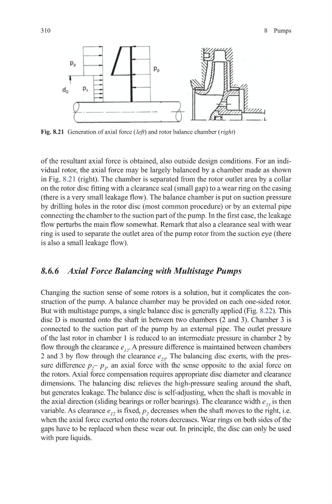
of the resultant axial force is obtained, also outside design conditions. For an individual rotor, the axial force may be largely balanced by a chamber made as shown
in Fig. 8.21 (right). The chamber is separated from the rotor outlet area by a collar
on the rotor disc fitting with a clearance seal (small gap) to a wear ring on the casing
(there is a very small leakage flow). The balance chamber is put on suction pressure
by drilling holes in the rotor disc (most common procedure) or by an external pipe
connecting the chamber to the suction part of the pump. In the first case, the leakage
flow perturbs the main flow somewhat. Remark that also a clearance seal with wear
ring is used to separate the outlet area of the pump rotor from the suction eye (there
is also a small leakage flow).
8.6.6 Axial Force Balancing with Multistage Pumps
Changing the suction sense of some rotors is a solution, but it complicates the construction of the pump. A balance chamber may be provided on each one-sided rotor.
But with multistage pumps, a single balance disc is generally applied (Fig. 8.22). This
disc D is mounted onto the shaft in between two chambers (2 and 3). Chamber 3 is
connected to the suction part of the pump by an external pipe. The outlet pressure
of the last rotor in chamber 1 is reduced to an intermediate pressure in chamber 2 by
flow through the clearance e 12 . A pressure difference is maintained between chambers
2 and 3 by flow through the clearance e 23 . The balancing disc exerts, with the pressure difference p 2 – p 3 , an axial force with the sense opposite to the axial force on
the rotors. Axial force compensation requires appropriate disc diameter and clearance
dimensions. The balancing disc relieves the high-pressure sealing around the shaft,
but generates leakage. The balance disc is self-adjusting, when the shaft is movable in
the axial direction (sliding bearings or roller bearings). The clearance width e 23 is then
variable. As clearance e 12 is fixed, p 2 decreases when the shaft moves to the right, i.e.
when the axial force exerted onto the rotors decreases. Wear rings on both sides of the
gaps have to be replaced when these wear out. In principle, the disc can only be used
with pure liquids.
Fig. 8.21 Generation of axial force ( left) and rotor balance chamber ( right)
310
of the resultant axial force is obtained, also outside design conditions. For an individual rotor, the axial force may be largely balanced by a chamber made as shown
in Fig. 8.21 (right). The chamber is separated from the rotor outlet area by a collar
on the rotor disc fitting with a clearance seal (small gap) to a wear ring on the casing
(there is a very small leakage flow). The balance chamber is put on suction pressure
by drilling holes in the rotor disc (most common procedure) or by an external pipe
connecting the chamber to the suction part of the pump. In the first case, the leakage
flow perturbs the main flow somewhat. Remark that also a clearance seal with wear
ring is used to separate the outlet area of the pump rotor from the suction eye (there
is also a small leakage flow).
8.6.6 Axial Force Balancing with Multistage Pumps
Changing the suction sense of some rotors is a solution, but it complicates the construction of the pump. A balance chamber may be provided on each one-sided rotor.
But with multistage pumps, a single balance disc is generally applied (Fig. 8.22). This
disc D is mounted onto the shaft in between two chambers (2 and 3). Chamber 3 is
connected to the suction part of the pump by an external pipe. The outlet pressure
of the last rotor in chamber 1 is reduced to an intermediate pressure in chamber 2 by
flow through the clearance e 12 . A pressure difference is maintained between chambers
2 and 3 by flow through the clearance e 23 . The balancing disc exerts, with the pressure difference p 2 – p 3 , an axial force with the sense opposite to the axial force on
the rotors. Axial force compensation requires appropriate disc diameter and clearance
dimensions. The balancing disc relieves the high-pressure sealing around the shaft,
but generates leakage. The balance disc is self-adjusting, when the shaft is movable in
the axial direction (sliding bearings or roller bearings). The clearance width e 23 is then
variable. As clearance e 12 is fixed, p 2 decreases when the shaft moves to the right, i.e.
when the axial force exerted onto the rotors decreases. Wear rings on both sides of the
gaps have to be replaced when these wear out. In principle, the disc can only be used
with pure liquids.
Fig. 8.21 Generation of axial force ( left) and rotor balance chamber ( right)