

8 Pumps
304
flow rate above the design value, acceleration occurs. The backpressure is then nonuniform, impairing the rotor efficiency. A second drawback may be a high bearing
load due to the radial force on the shaft. Both drawbacks are attenuated by mounting
two partial volutes (Fig. 8.15, right), instead of one volute.
In principle, a volute could consist of two parallel walls at distance equal to the
rotor outlet width, and an external wall with logarithmic spiral shape. This form is
disadvantageous since the volute then takes much radial space and the transition
from the rectangular final section towards a circular outlet becomes very long. The
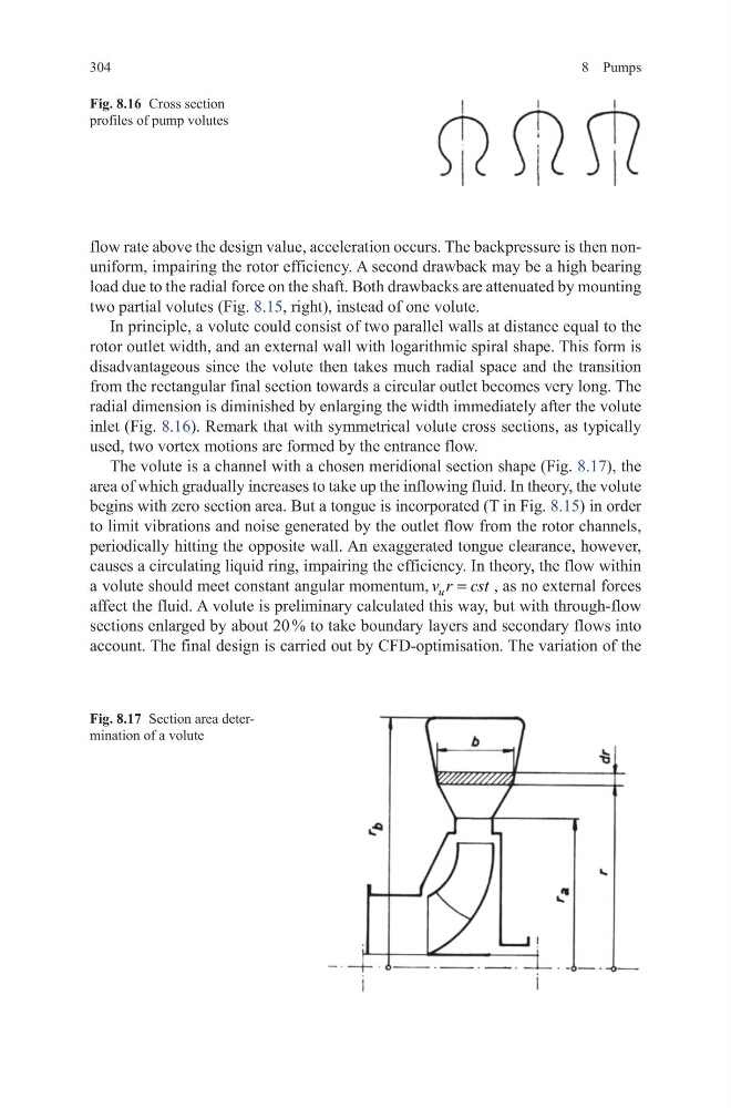
radial dimension is diminished by enlarging the width immediately after the volute
inlet (Fig. 8.16). Remark that with symmetrical volute cross sections, as typically
used, two vortex motions are formed by the entrance flow.
The volute is a channel with a chosen meridional section shape (Fig. 8.17), the
area of which gradually increases to take up the inflowing fluid. In theory, the volute
begins with zero section area. But a tongue is incorporated (T in Fig. 8.15) in order
to limit vibrations and noise generated by the outlet flow from the rotor channels,
periodically hitting the opposite wall. An exaggerated tongue clearance, however,
causes a circulating liquid ring, impairing the efficiency. In theory, the flow within
a volute should meet constant angular momentum, u
v r cst
=
, as no external forces
affect the fluid. A volute is preliminary calculated this way, but with through-flow
sections enlarged by about 20 % to take boundary layers and secondary flows into
account. The final design is carried out by CFD-optimisation. The variation of the
Fig. 8.17 Section area determination of a volute
Fig. 8.16 Cross section
profiles of pump volutes
304
flow rate above the design value, acceleration occurs. The backpressure is then nonuniform, impairing the rotor efficiency. A second drawback may be a high bearing
load due to the radial force on the shaft. Both drawbacks are attenuated by mounting
two partial volutes (Fig. 8.15, right), instead of one volute.
In principle, a volute could consist of two parallel walls at distance equal to the
rotor outlet width, and an external wall with logarithmic spiral shape. This form is
disadvantageous since the volute then takes much radial space and the transition
from the rectangular final section towards a circular outlet becomes very long. The
radial dimension is diminished by enlarging the width immediately after the volute
inlet (Fig. 8.16). Remark that with symmetrical volute cross sections, as typically
used, two vortex motions are formed by the entrance flow.
The volute is a channel with a chosen meridional section shape (Fig. 8.17), the
area of which gradually increases to take up the inflowing fluid. In theory, the volute
begins with zero section area. But a tongue is incorporated (T in Fig. 8.15) in order
to limit vibrations and noise generated by the outlet flow from the rotor channels,
periodically hitting the opposite wall. An exaggerated tongue clearance, however,
causes a circulating liquid ring, impairing the efficiency. In theory, the flow within
a volute should meet constant angular momentum, u
v r cst
=
, as no external forces
affect the fluid. A volute is preliminary calculated this way, but with through-flow
sections enlarged by about 20 % to take boundary layers and secondary flows into
account. The final design is carried out by CFD-optimisation. The variation of the
Fig. 8.17 Section area determination of a volute
Fig. 8.16 Cross section
profiles of pump volutes