

7 Dynamic Similitude
280
7.7.4. A 1/10 scale model should be built of a hydraulic turbine with 40 MW
shaft power, 50 m manometric head, 100 rpm rotational speed and overall efficiency
0.90. The available head in the laboratory is 6 m. Determine the rotational speed of
the model, the expected flow rate and the shaft power, with similar flow. Correct
the efficiency for imperfect similitude by means of Moody’s formula (7.13). Apply
the correction to the overall efficiency, in other words assume volumetric and mechanical efficiencies both equal to unity. Correct power and flow rate by the method
of Casey et al. (7.10–7.12). Note that head and work have to be switched in these
formulae for use with turbines. Observe that the efficiency correction is quite big
with a 1/10 scale ratio.
A: H m = 6.0 m, Q = 0.292 m
3
/s, n = 333.8 rpm, η = 0.780, P = 13.42 kW.
7.7.5. A throttle valve connected in series with a pump is a traditional way of
flow rate adjustment, as discussed in Sect. 7.3. An alternative way is fitting a bypass
line to the pump connecting the discharge side to the suction side with the throttle
vale in the bypass line. The net flow rate of the pump is then reduced by circulating
part of the flow rate. Determine the net characteristic of the pump combined with
the valve in both cases. Observe that with the valve in series the net head is mainly
reduced for high flow rate while with the valve in parallel the net head is mainly
reduced for low flow rate.
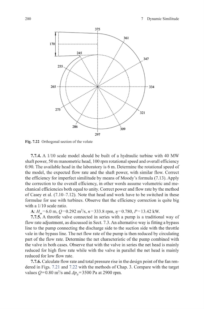
7.7.6. Calculate flow rate and total pressure rise in the design point of the fan rendered in Figs. 7.21 and 7.22 with the methods of Chap. 3. Compare with the target
values Q = 0.80 m
3
/s and Δp 0 = 3500 Pa at 2900 rpm.
Fig. 7.22 Orthogonal section of the volute
280
7.7.4. A 1/10 scale model should be built of a hydraulic turbine with 40 MW
shaft power, 50 m manometric head, 100 rpm rotational speed and overall efficiency
0.90. The available head in the laboratory is 6 m. Determine the rotational speed of
the model, the expected flow rate and the shaft power, with similar flow. Correct
the efficiency for imperfect similitude by means of Moody’s formula (7.13). Apply
the correction to the overall efficiency, in other words assume volumetric and mechanical efficiencies both equal to unity. Correct power and flow rate by the method
of Casey et al. (7.10–7.12). Note that head and work have to be switched in these
formulae for use with turbines. Observe that the efficiency correction is quite big
with a 1/10 scale ratio.
A: H m = 6.0 m, Q = 0.292 m
3
/s, n = 333.8 rpm, η = 0.780, P = 13.42 kW.
7.7.5. A throttle valve connected in series with a pump is a traditional way of
flow rate adjustment, as discussed in Sect. 7.3. An alternative way is fitting a bypass
line to the pump connecting the discharge side to the suction side with the throttle
vale in the bypass line. The net flow rate of the pump is then reduced by circulating
part of the flow rate. Determine the net characteristic of the pump combined with
the valve in both cases. Observe that with the valve in series the net head is mainly
reduced for high flow rate while with the valve in parallel the net head is mainly
reduced for low flow rate.
7.7.6. Calculate flow rate and total pressure rise in the design point of the fan rendered in Figs. 7.21 and 7.22 with the methods of Chap. 3. Compare with the target
values Q = 0.80 m
3
/s and Δp 0 = 3500 Pa at 2900 rpm.
Fig. 7.22 Orthogonal section of the volute