

7.5 Series and Parallel Connection
273
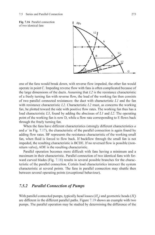
one of the fans would break down, with reverse flow impeded, the other fan would
operate in point C. Impeding reverse flow with fans is often complicated because of
the large dimensions of the ducts. Assuming that L2 is the resistance characteristic
of a freely turning fan with reverse flow, the load of the working fan then consists
of two parallel connected resistances: the duct with characteristic L1 and the fan
with resistance characteristic L2. Characteristic L2 must, as concerns the working
fan, be plotted toward the side with positive flow rates. The working fan thus has a
load characteristic L3, found by adding the abscissas of L1 and L2. The operating
point of the working fan is now D, while a flow rate corresponding to E flows back
through the freely turning fan.
When the fans have different characteristics (strongly different characteristics a
and a’ in Fig. 7.17), the characteristic of the parallel connection is again found by
adding flow rates. BF represents the resistance characteristic of the working small
fan, when fluid is forced to flow back. If backflow through the small fan is not
impeded, the resulting characteristic is BCDE. If no reversed flow is possible (nonreturn valve), ADE is the resulting characteristic.
Parallel operation becomes more difficult with fans having a minimum and a
maximum in their characteristic. Parallel connection of two identical fans with forward curved blades (Fig. 7.18) results in several possible branches for the characteristic of the parallel connection. Certain load characteristics intersect the system
characteristic at several points. The fans in parallel connection may shuttle then
between several operating points (exceptional behaviour).
7.5.2 Parallel Connection of Pumps
With parallel connected pumps, typically head losses ( H li ) and geometric heads ( H i )
are different in the different parallel paths. Figure 7.19 shows an example with two
pumps. The parallel operation may be studied by determining the difference of the
Fig. 7.16 Parallel connection
of two identical fans
273
one of the fans would break down, with reverse flow impeded, the other fan would
operate in point C. Impeding reverse flow with fans is often complicated because of
the large dimensions of the ducts. Assuming that L2 is the resistance characteristic
of a freely turning fan with reverse flow, the load of the working fan then consists
of two parallel connected resistances: the duct with characteristic L1 and the fan
with resistance characteristic L2. Characteristic L2 must, as concerns the working
fan, be plotted toward the side with positive flow rates. The working fan thus has a
load characteristic L3, found by adding the abscissas of L1 and L2. The operating
point of the working fan is now D, while a flow rate corresponding to E flows back
through the freely turning fan.
When the fans have different characteristics (strongly different characteristics a
and a’ in Fig. 7.17), the characteristic of the parallel connection is again found by
adding flow rates. BF represents the resistance characteristic of the working small
fan, when fluid is forced to flow back. If backflow through the small fan is not
impeded, the resulting characteristic is BCDE. If no reversed flow is possible (nonreturn valve), ADE is the resulting characteristic.
Parallel operation becomes more difficult with fans having a minimum and a
maximum in their characteristic. Parallel connection of two identical fans with forward curved blades (Fig. 7.18) results in several possible branches for the characteristic of the parallel connection. Certain load characteristics intersect the system
characteristic at several points. The fans in parallel connection may shuttle then
between several operating points (exceptional behaviour).
7.5.2 Parallel Connection of Pumps
With parallel connected pumps, typically head losses ( H li ) and geometric heads ( H i )
are different in the different parallel paths. Figure 7.19 shows an example with two
pumps. The parallel operation may be studied by determining the difference of the
Fig. 7.16 Parallel connection
of two identical fans