

3
1.2 Examples of Axial Turbomachines
multiplied with radius r), called blade speed. The absolute flow velocity vector (
v ) is
the vector sum of the blade speed (
u ) and the relative flow velocity vector (
w ).
The components have the following functions.
• Inlet and guide ring:
− guiding fluid to the rotor and distributing it over the rotor
− generating kinetic energy: v 1
2
2
/ .
The kinetic energy originates from a pressure drop, where pressure upstream of the
machine is built up from gravitational potential energy (see the further Eq. 1.5).
Acceleration of the flow with hydraulic turbines such as in Fig. 1.1 is never strong.
Guiding the fluid is the main function. We here apply the terms guide ring and guide
vanes. Stationary objects guiding the flow are typically called vanes, while the term
blade is mostly used for a rotary object, but the term blade is also used for either.
In other machines, flow acceleration may be the most important, as with steam
turbines. The stator is then said to be composed from nozzles and the term nozzle
ring is used.
• Rotor (or runner): energy extraction from the flow.
In the relative frame: w
w
2
2
1
2
2
2
/
/
>
. Kinetic energy is generated, corresponding to pressure drop (see the further Eq. 1.13). In the absolute frame, kinetic energy decreases:
2
2
2
1
v / 2 v / 2
<
. Both the decrease of pressure and kinetic energy
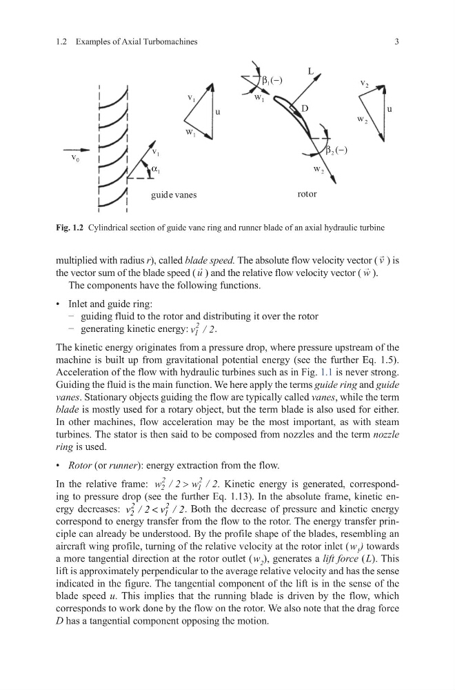
correspond to energy transfer from the flow to the rotor. The energy transfer principle can already be understood. By the profile shape of the blades, resembling an
aircraft wing profile, turning of the relative velocity at the rotor inlet ( w 1 ) towards
a more tangential direction at the rotor outlet ( w 2 ), generates a lift force ( L). This
lift is approximately perpendicular to the average relative velocity and has the sense
indicated in the figure. The tangential component of the lift is in the sense of the
blade speed u. This implies that the running blade is driven by the flow, which
corresponds to work done by the flow on the rotor. We also note that the drag force
D has a tangential component opposing the motion.
Fig. 1.2 Cylindrical section of guide vane ring and runner blade of an axial hydraulic turbine
guide vanes
rotor
L
D
u
u
2
v
2
w
1
v
1
w
1
v
2
w
1
w
1
α
)
(
1 −
β
)
(
2 −
β
0
v
1.2 Examples of Axial Turbomachines
multiplied with radius r), called blade speed. The absolute flow velocity vector (
v ) is
the vector sum of the blade speed (
u ) and the relative flow velocity vector (
w ).
The components have the following functions.
• Inlet and guide ring:
− guiding fluid to the rotor and distributing it over the rotor
− generating kinetic energy: v 1
2
2
/ .
The kinetic energy originates from a pressure drop, where pressure upstream of the
machine is built up from gravitational potential energy (see the further Eq. 1.5).
Acceleration of the flow with hydraulic turbines such as in Fig. 1.1 is never strong.
Guiding the fluid is the main function. We here apply the terms guide ring and guide
vanes. Stationary objects guiding the flow are typically called vanes, while the term
blade is mostly used for a rotary object, but the term blade is also used for either.
In other machines, flow acceleration may be the most important, as with steam
turbines. The stator is then said to be composed from nozzles and the term nozzle
ring is used.
• Rotor (or runner): energy extraction from the flow.
In the relative frame: w
w
2
2
1
2
2
2
/
/
>
. Kinetic energy is generated, corresponding to pressure drop (see the further Eq. 1.13). In the absolute frame, kinetic energy decreases:
2
2
2
1
v / 2 v / 2
<
. Both the decrease of pressure and kinetic energy
correspond to energy transfer from the flow to the rotor. The energy transfer principle can already be understood. By the profile shape of the blades, resembling an
aircraft wing profile, turning of the relative velocity at the rotor inlet ( w 1 ) towards
a more tangential direction at the rotor outlet ( w 2 ), generates a lift force ( L). This
lift is approximately perpendicular to the average relative velocity and has the sense
indicated in the figure. The tangential component of the lift is in the sense of the
blade speed u. This implies that the running blade is driven by the flow, which
corresponds to work done by the flow on the rotor. We also note that the drag force
D has a tangential component opposing the motion.
Fig. 1.2 Cylindrical section of guide vane ring and runner blade of an axial hydraulic turbine
guide vanes
rotor
L
D
u
u
2
v
2
w
1
v
1
w
1
v
2
w
1
w
1
α
)
(
1 −
β
)
(
2 −
β
0
v