

245
sure difference across the rotor makes the analogy with a Laval impulse type steam
turbine. The Girard turbine can be analysed similarly. The only essential difference
comes from the gravitational potential energy in the rotor, which creates a slight
acceleration such that the kinematic degree of reaction becomes slightly positive,
where it is slightly negative with a Laval turbine.
Analyse the flow through the Girard turbine with a mean line representation of
the flow (one-dimensional representation). Assume admission over 360º to the stator. Take as outlet angle of the nozzle vanes 1 60
°
=
a
and consider the operating
point with exact axial outlet of the rotor, seen in the absolute frame: 2 0 .
°
=
a
Determine losses in stator and rotor cascades with Soderberg’s formula. Take the aspect
ratio of vanes and blades (height to axial chord) equal to unity. Assume constant
axial component of the velocity in the rotor.
a. Determine axial and tangential components of the absolute velocity at the outlet
of the stator vanes. Derive the outlet velocity from the work equation in the stator. The height difference between the water surface in the water chamber and
the outlet of the stator vanes is 3.00 m.
b. Determine the blade speed such that the absolute velocity at rotor outlet is in
the axial direction. Derive this speed from the work equation in the rotor. Pay
attention to the small acceleration in the rotor. The consequence is that rotor
blades cannot be exactly symmetrical for constant axial velocity. The computation requires iteration for the loss coefficient of the rotor. A starting value may
be determined from a computation ignoring rotor loss. The height difference
between inlet and outlet of the rotor is 0.30 m. Ignore the small gap between stator and rotor.
6.10 Exercises
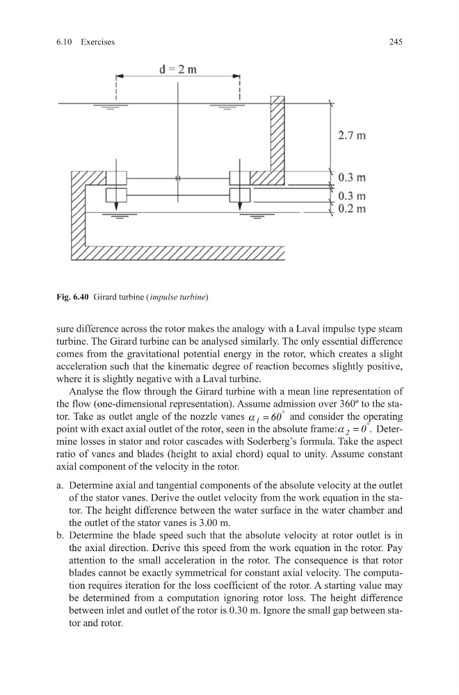
Fig. 6.40 Girard turbine ( impulse turbine)
sure difference across the rotor makes the analogy with a Laval impulse type steam
turbine. The Girard turbine can be analysed similarly. The only essential difference
comes from the gravitational potential energy in the rotor, which creates a slight
acceleration such that the kinematic degree of reaction becomes slightly positive,
where it is slightly negative with a Laval turbine.
Analyse the flow through the Girard turbine with a mean line representation of
the flow (one-dimensional representation). Assume admission over 360º to the stator. Take as outlet angle of the nozzle vanes 1 60
°
=
a
and consider the operating
point with exact axial outlet of the rotor, seen in the absolute frame: 2 0 .
°
=
a
Determine losses in stator and rotor cascades with Soderberg’s formula. Take the aspect
ratio of vanes and blades (height to axial chord) equal to unity. Assume constant
axial component of the velocity in the rotor.
a. Determine axial and tangential components of the absolute velocity at the outlet
of the stator vanes. Derive the outlet velocity from the work equation in the stator. The height difference between the water surface in the water chamber and
the outlet of the stator vanes is 3.00 m.
b. Determine the blade speed such that the absolute velocity at rotor outlet is in
the axial direction. Derive this speed from the work equation in the rotor. Pay
attention to the small acceleration in the rotor. The consequence is that rotor
blades cannot be exactly symmetrical for constant axial velocity. The computation requires iteration for the loss coefficient of the rotor. A starting value may
be determined from a computation ignoring rotor loss. The height difference
between inlet and outlet of the rotor is 0.30 m. Ignore the small gap between stator and rotor.
6.10 Exercises
Fig. 6.40 Girard turbine ( impulse turbine)