

202
6 Steam Turbines
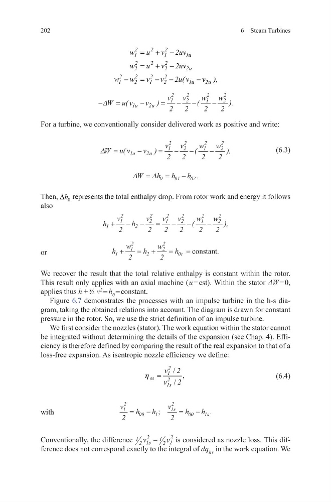
For a turbine, we conventionally consider delivered work as positive and write:
(6.3)
Then, 0
h
∆ represents the total enthalpy drop. From rotor work and energy it follows
also
or
h
w
h
w
h r
1
1
2
2
2
2
0
2
2
+
= +
=
= constant.
We recover the result that the total relative enthalpy is constant within the rotor.
This result only applies with an axial machine ( u = cst). Within the stator ΔW = 0,
applies thus h + ½ v
2
= h 0 = constant.
Figure 6.7 demonstrates the processes with an impulse turbine in the h-s diagram, taking the obtained relations into account. The diagram is drawn for constant
pressure in the rotor. So, we use the strict definition of an impulse turbine.
We first consider the nozzles (stator). The work equation within the stator cannot
be integrated without determining the details of the expansion (see Chap. 4). Efficiency is therefore defined by comparing the result of the real expansion to that of a
loss-free expansion. As isentropic nozzle efficiency we define:
(6.4)
with
v
h
h
v
h
h
s
s
1
2
00
1
1
2
00
1
2
2
=
−
=
−
;
.
Conventionally, the difference 1 2 1
2
1 2 1
2
v
v
s −
is considered as nozzle loss. This difference does not correspond exactly to the integral of dq irr in the work equation. We
2
2
2
1
1
1u
2
2
2
2
2
2u
2
2
2
2
1
2
1
2
1u
2u
w
u v 2uv
w
u v 2uv
w w
v v 2u( v
v ),
= + −
= + −
−
= − −
−
−
=
−
=
− −
−
∆W u v
v
v
v
w
w
u
u
(
)
(
) .
1
2
1
2
2
2
1
2
2
2
2
2
2
2
∆W u v
v
v
v
w
w
u
u
=
−
=
− −
−
(
)
(
) ,
1
2
1
2
2
2
1
2
2
2
2
2
2
2
∆
∆
W
h h
h
=
=
−
0
0 1
02 .
h
v
h
v
v
v
w
w
1
1
2
2
2
2
1
2
2
2
1
2
2
2
2
2
2
2
2
2
+ − −
=
− −
−
(
) ,
/ ,
/
2
1
ss
2
1s
v 2
v 2
h =
6 Steam Turbines
For a turbine, we conventionally consider delivered work as positive and write:
(6.3)
Then, 0
h
∆ represents the total enthalpy drop. From rotor work and energy it follows
also
or
h
w
h
w
h r
1
1
2
2
2
2
0
2
2
+
= +
=
= constant.
We recover the result that the total relative enthalpy is constant within the rotor.
This result only applies with an axial machine ( u = cst). Within the stator ΔW = 0,
applies thus h + ½ v
2
= h 0 = constant.
Figure 6.7 demonstrates the processes with an impulse turbine in the h-s diagram, taking the obtained relations into account. The diagram is drawn for constant
pressure in the rotor. So, we use the strict definition of an impulse turbine.
We first consider the nozzles (stator). The work equation within the stator cannot
be integrated without determining the details of the expansion (see Chap. 4). Efficiency is therefore defined by comparing the result of the real expansion to that of a
loss-free expansion. As isentropic nozzle efficiency we define:
(6.4)
with
v
h
h
v
h
h
s
s
1
2
00
1
1
2
00
1
2
2
=
−
=
−
;
.
Conventionally, the difference 1 2 1
2
1 2 1
2
v
v
s −
is considered as nozzle loss. This difference does not correspond exactly to the integral of dq irr in the work equation. We
2
2
2
1
1
1u
2
2
2
2
2
2u
2
2
2
2
1
2
1
2
1u
2u
w
u v 2uv
w
u v 2uv
w w
v v 2u( v
v ),
= + −
= + −
−
= − −
−
−
=
−
=
− −
−
∆W u v
v
v
v
w
w
u
u
(
)
(
) .
1
2
1
2
2
2
1
2
2
2
2
2
2
2
∆W u v
v
v
v
w
w
u
u
=
−
=
− −
−
(
)
(
) ,
1
2
1
2
2
2
1
2
2
2
2
2
2
2
∆
∆
W
h h
h
=
=
−
0
0 1
02 .
h
v
h
v
v
v
w
w
1
1
2
2
2
2
1
2
2
2
1
2
2
2
2
2
2
2
2
2
+ − −
=
− −
−
(
) ,
/ ,
/
2
1
ss
2
1s
v 2
v 2
h =