

189
5.8 Laboratory Test of a Centrifugal Pump
5.8 Laboratory Test of a Centrifugal Pump
5.8.1 Test Rig
The pump is a single-stage centrifugal pump with double pressure pipe, meant as a
fire brigade pump (low weight, high rotational speed, high flow rate and sufficient
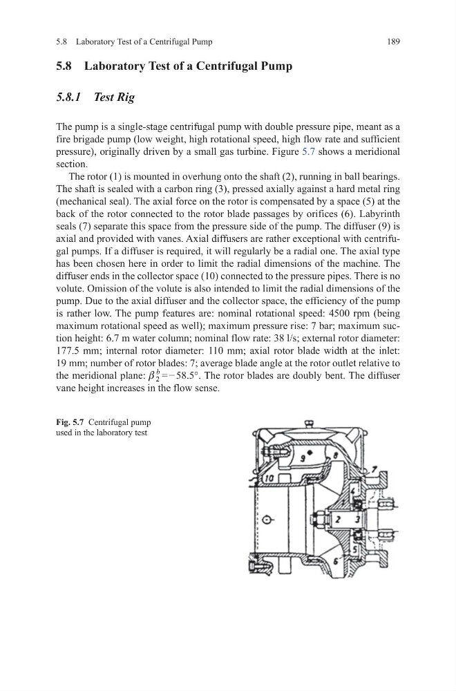
pressure), originally driven by a small gas turbine. Figure 5.7 shows a meridional
section.
The rotor (1) is mounted in overhung onto the shaft (2), running in ball bearings.
The shaft is sealed with a carbon ring (3), pressed axially against a hard metal ring
(mechanical seal). The axial force on the rotor is compensated by a space (5) at the
back of the rotor connected to the rotor blade passages by orifices (6). Labyrinth
seals (7) separate this space from the pressure side of the pump. The diffuser (9) is
axial and provided with vanes. Axial diffusers are rather exceptional with centrifugal pumps. If a diffuser is required, it will regularly be a radial one. The axial type
has been chosen here in order to limit the radial dimensions of the machine. The
diffuser ends in the collector space (10) connected to the pressure pipes. There is no
volute. Omission of the volute is also intended to limit the radial dimensions of the
pump. Due to the axial diffuser and the collector space, the efficiency of the pump
is rather low. The pump features are: nominal rotational speed: 4500 rpm (being
maximum rotational speed as well); maximum pressure rise: 7 bar; maximum suction height: 6.7 m water column; nominal flow rate: 38 l/s; external rotor diameter:
177.5 mm; internal rotor diameter: 110 mm; axial rotor blade width at the inlet:
19 mm; number of rotor blades: 7; average blade angle at the rotor outlet relative to
the meridional plane: 2
b
b = − 58.5°. The rotor blades are doubly bent. The diffuser
vane height increases in the flow sense.
Fig. 5.7 Centrifugal pump
used in the laboratory test
5.8 Laboratory Test of a Centrifugal Pump
5.8 Laboratory Test of a Centrifugal Pump
5.8.1 Test Rig
The pump is a single-stage centrifugal pump with double pressure pipe, meant as a
fire brigade pump (low weight, high rotational speed, high flow rate and sufficient
pressure), originally driven by a small gas turbine. Figure 5.7 shows a meridional
section.
The rotor (1) is mounted in overhung onto the shaft (2), running in ball bearings.
The shaft is sealed with a carbon ring (3), pressed axially against a hard metal ring
(mechanical seal). The axial force on the rotor is compensated by a space (5) at the
back of the rotor connected to the rotor blade passages by orifices (6). Labyrinth
seals (7) separate this space from the pressure side of the pump. The diffuser (9) is
axial and provided with vanes. Axial diffusers are rather exceptional with centrifugal pumps. If a diffuser is required, it will regularly be a radial one. The axial type
has been chosen here in order to limit the radial dimensions of the machine. The
diffuser ends in the collector space (10) connected to the pressure pipes. There is no
volute. Omission of the volute is also intended to limit the radial dimensions of the
pump. Due to the axial diffuser and the collector space, the efficiency of the pump
is rather low. The pump features are: nominal rotational speed: 4500 rpm (being
maximum rotational speed as well); maximum pressure rise: 7 bar; maximum suction height: 6.7 m water column; nominal flow rate: 38 l/s; external rotor diameter:
177.5 mm; internal rotor diameter: 110 mm; axial rotor blade width at the inlet:
19 mm; number of rotor blades: 7; average blade angle at the rotor outlet relative to
the meridional plane: 2
b
b = − 58.5°. The rotor blades are doubly bent. The diffuser
vane height increases in the flow sense.
Fig. 5.7 Centrifugal pump
used in the laboratory test