

179
5.3 Flow Rate Measurement
5.3.3 Pressure Drop Devices
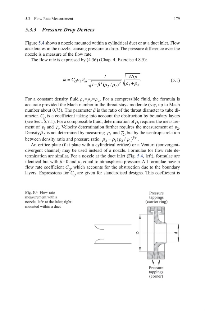
Figure 5.4 shows a nozzle mounted within a cylindrical duct or at a duct inlet. Flow
accelerates in the nozzle, causing pressure to drop. The pressure difference over the
nozzle is a measure of the flow rate.
The flow rate is expressed by (4.36) (Chap. 4, Exercise 4.8.5):
(5.1)
For a constant density fluid ρ 1 = ρ 2 = ρ m . For a compressible fluid, the formula is
accurate provided the Mach number in the throat stays moderate (say, up to Mach
number about 0.75). The parameter β is the ratio of the throat diameter to tube diameter. C Q is a coefficient taking into account the obstruction by boundary layers
(see Sect. 5.7.1). For a compressible fluid, determination of 1
r requires the measurement of p 1 and T 1 . Velocity determination further requires the measurement of p 2 .
Density 2
r is not determined by measuring p 2 and T 2 , but by the isentropic relation
between density ratio and pressure ratio:
1/
2
1
2
1
( / )
p p
g
r
r
=
.
An orifice plate (flat plate with a cylindrical orifice) or a Venturi (convergentdivergent channel) may be used instead of a nozzle. Formulae for flow rate determination are similar. For a nozzle at the duct inlet (Fig. 5.4, left), formulae are
identical but with β = 0 and p 1 equal to atmospheric pressure. All formulae have a
flow rate coefficient C Q , which accounts for the obstruction due to the boundary
layers. Expressions for C Q are given for standardised designs. This coefficient is
.
( / )
Q 2 th
4
2
1
2
2
1
1
4 p
m C
A
1
D
r
r r
b r r
=
+
−
Fig. 5.4 Flow rate
measurement with a
nozzle; left: at the inlet; right:
mounted within a duct
5.3 Flow Rate Measurement
5.3.3 Pressure Drop Devices
Figure 5.4 shows a nozzle mounted within a cylindrical duct or at a duct inlet. Flow
accelerates in the nozzle, causing pressure to drop. The pressure difference over the
nozzle is a measure of the flow rate.
The flow rate is expressed by (4.36) (Chap. 4, Exercise 4.8.5):
(5.1)
For a constant density fluid ρ 1 = ρ 2 = ρ m . For a compressible fluid, the formula is
accurate provided the Mach number in the throat stays moderate (say, up to Mach
number about 0.75). The parameter β is the ratio of the throat diameter to tube diameter. C Q is a coefficient taking into account the obstruction by boundary layers
(see Sect. 5.7.1). For a compressible fluid, determination of 1
r requires the measurement of p 1 and T 1 . Velocity determination further requires the measurement of p 2 .
Density 2
r is not determined by measuring p 2 and T 2 , but by the isentropic relation
between density ratio and pressure ratio:
1/
2
1
2
1
( / )
p p
g
r
r
=
.
An orifice plate (flat plate with a cylindrical orifice) or a Venturi (convergentdivergent channel) may be used instead of a nozzle. Formulae for flow rate determination are similar. For a nozzle at the duct inlet (Fig. 5.4, left), formulae are
identical but with β = 0 and p 1 equal to atmospheric pressure. All formulae have a
flow rate coefficient C Q , which accounts for the obstruction due to the boundary
layers. Expressions for C Q are given for standardised designs. This coefficient is
.
( / )
Q 2 th
4
2
1
2
2
1
1
4 p
m C
A
1
D
r
r r
b r r
=
+
−
Fig. 5.4 Flow rate
measurement with a
nozzle; left: at the inlet; right:
mounted within a duct