

118
3 Fans
purely empirical formulae are employed for estimating the necessary rotor solidity
with radial machines
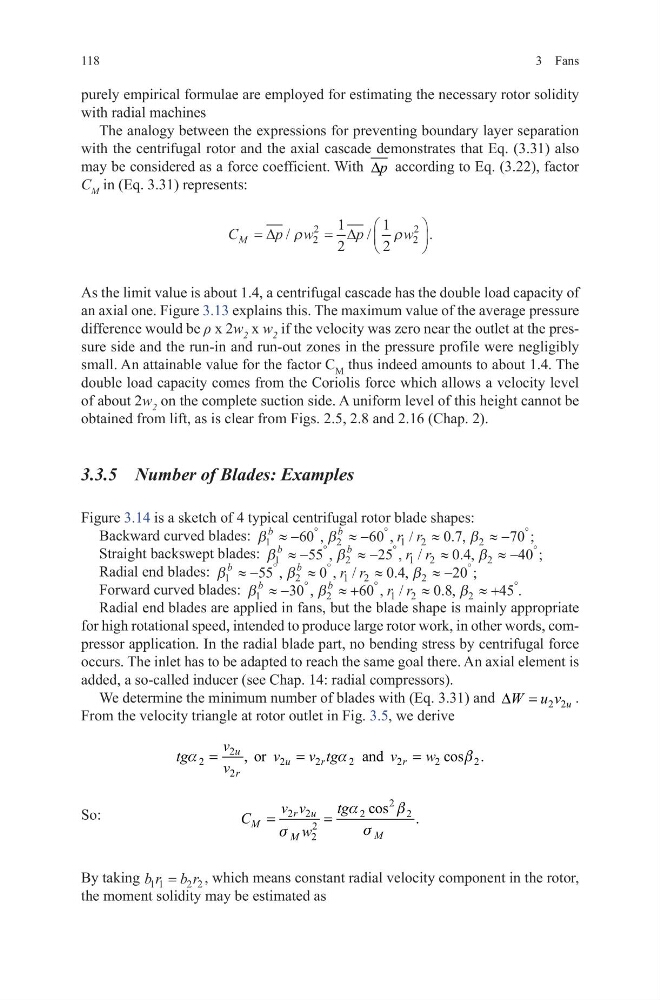
The analogy between the expressions for preventing boundary layer separation
with the centrifugal rotor and the axial cascade demonstrates that Eq. (3.31) also
may be considered as a force coefficient. With p
∆ according to Eq. (3.22), factor
C M in (Eq. 3.31) represents:
As the limit value is about 1.4, a centrifugal cascade has the double load capacity of
an axial one. Figure 3.13 explains this. The maximum value of the average pressure
difference would be ρ x 2w 2 x w 2 if the velocity was zero near the outlet at the pressure side and the run-in and run-out zones in the pressure profile were negligibly
small. An attainable value for the factor C M thus indeed amounts to about 1.4. The
double load capacity comes from the Coriolis force which allows a velocity level
of about 2w 2 on the complete suction side. A uniform level of this height cannot be
obtained from lift, as is clear from Figs. 2.5, 2.8 and 2.16 (Chap. 2).
3.3.5 Number of Blades: Examples
Figure 3.14 is a sketch of 4 typical centrifugal rotor blade shapes:
Backward curved blades: β
β
β
1
2
1 2
2
60
60
0 7
70
b
b
r r
≈ −
≈ −
≈
≈−
°
°
°
,
, /
. ,
;
Straight backswept blades: β
β
β
1
2
1 2
2
55
25
0 4
40
b
b
r r
≈ −
≈ −
≈
≈−
°
°
°
,
, /
. ,
;
Radial end blades: β
β
β
1
2
1 2
2
55
0
04
2 0
b
b
r r
≈ −
≈
≈
≈ −
°
°
°
,
, /
. ,
;
Forward curved blades: β
β
β
1
2
1 2
2
30
60
0 8
45
b
b
r r
≈ −
≈ +
≈
≈+
°
°
°
,
, /
. ,
.
Radial end blades are applied in fans, but the blade shape is mainly appropriate
for high rotational speed, intended to produce large rotor work, in other words, compressor application. In the radial blade part, no bending stress by centrifugal force
occurs. The inlet has to be adapted to reach the same goal there. An axial element is
added, a so-called inducer (see Chap. 14: radial compressors).
We determine the minimum number of blades with (Eq. 3.31) and
2 2u
W u v
∆ =
.
From the velocity triangle at rotor outlet in Fig. 3.5, we derive
So:
By taking b r b r
1 1
2 2
=
, which means constant radial velocity component in the rotor,
the moment solidity may be estimated as
C
p w
p
w
M =
=
∆
∆
/
/
.
ρ
ρ
2
2
2
2
1
2
1
2
2
2
2
2
2
2
2
2
2
, or
and
cos .
u
u
r
r
r
v
tg
v
v tg
v
w
v
a
a
b
=
=
=
2
2 2
2
2
2
2
cos
.
r u
M
M
M
v v
tg
C
w
a
b
s
s
=
=
3 Fans
purely empirical formulae are employed for estimating the necessary rotor solidity
with radial machines
The analogy between the expressions for preventing boundary layer separation
with the centrifugal rotor and the axial cascade demonstrates that Eq. (3.31) also
may be considered as a force coefficient. With p
∆ according to Eq. (3.22), factor
C M in (Eq. 3.31) represents:
As the limit value is about 1.4, a centrifugal cascade has the double load capacity of
an axial one. Figure 3.13 explains this. The maximum value of the average pressure
difference would be ρ x 2w 2 x w 2 if the velocity was zero near the outlet at the pressure side and the run-in and run-out zones in the pressure profile were negligibly
small. An attainable value for the factor C M thus indeed amounts to about 1.4. The
double load capacity comes from the Coriolis force which allows a velocity level
of about 2w 2 on the complete suction side. A uniform level of this height cannot be
obtained from lift, as is clear from Figs. 2.5, 2.8 and 2.16 (Chap. 2).
3.3.5 Number of Blades: Examples
Figure 3.14 is a sketch of 4 typical centrifugal rotor blade shapes:
Backward curved blades: β
β
β
1
2
1 2
2
60
60
0 7
70
b
b
r r
≈ −
≈ −
≈
≈−
°
°
°
,
, /
. ,
;
Straight backswept blades: β
β
β
1
2
1 2
2
55
25
0 4
40
b
b
r r
≈ −
≈ −
≈
≈−
°
°
°
,
, /
. ,
;
Radial end blades: β
β
β
1
2
1 2
2
55
0
04
2 0
b
b
r r
≈ −
≈
≈
≈ −
°
°
°
,
, /
. ,
;
Forward curved blades: β
β
β
1
2
1 2
2
30
60
0 8
45
b
b
r r
≈ −
≈ +
≈
≈+
°
°
°
,
, /
. ,
.
Radial end blades are applied in fans, but the blade shape is mainly appropriate
for high rotational speed, intended to produce large rotor work, in other words, compressor application. In the radial blade part, no bending stress by centrifugal force
occurs. The inlet has to be adapted to reach the same goal there. An axial element is
added, a so-called inducer (see Chap. 14: radial compressors).
We determine the minimum number of blades with (Eq. 3.31) and
2 2u
W u v
∆ =
.
From the velocity triangle at rotor outlet in Fig. 3.5, we derive
So:
By taking b r b r
1 1
2 2
=
, which means constant radial velocity component in the rotor,
the moment solidity may be estimated as
C
p w
p
w
M =
=
∆
∆
/
/
.
ρ
ρ
2
2
2
2
1
2
1
2
2
2
2
2
2
2
2
2
2
, or
and
cos .
u
u
r
r
r
v
tg
v
v tg
v
w
v
a
a
b
=
=
=
2
2 2
2
2
2
2
cos
.
r u
M
M
M
v v
tg
C
w
a
b
s
s
=
=