

115
With Pfleiderer’s representation, the characteristic 1
0
p
r ∆
as a function of the flow
rate is a straight line that intersects the theoretical characteristic with an infinite
number of blades on the abscissa (with β 2 ≠ 0). This representation is simplifying
and with small blade overlap, the work reduction factor certainly is flow rate dependent.
The turbomachinery literature contains many formulae for the slip factor or the
work reduction factor. They all give approximate results, best workable near the design operating point. Wiesner’s formula is best with high solidity rotors. Pfleiderer’s
formula is best with small blade overlap. However, no formula is perfect and even
nowadays, research on new formulae continues. Recent proposals are by von Backström [11] and by Qiu et al. [10]. The slip factor and the work reduction factor are
flow rate dependent, as shown in this last study, but it is not possible to express this
dependency in a simple way.
3.3.4 Number of Blades and Solidity: Pfleiderer Moment
Coefficient
When a rotor is provided with many blades, slip is small and rotor work is close to
the maximum attainable. This is no optimum choice regarding efficiency, as a large
blade surface implies a great friction surface. Work reduction due to slip is no loss
in itself, but the effect of losses between the driving motor and the rotor (so-called
mechanical losses, see Sect. 3.5.1) becomes important with a very small rotor work.
So, except for cases with small rotor work, a rather significant slip is acceptable.
This implies that the optimum number of blades for efficiency is mostly quite close
to the minimum that is sufficient to realise an attached flow. Of course, other reasons may require a larger number. The most common reason is margin against flow
separation at flow rate lower than the design flow rate (see Sect. 3.3.5).
From the flow pattern in Fig. 3.9 we learn that two criteria shall be met to avoid
separation at the rotor outlet. Firstly, the number of blades must be large enough to
prevent the Coriolis force and lift force from generating reversed flow at the pressure side. Secondly, blade load should not become so high that separation occurs
near the trailing edge at the suction side. The pressure at the suction side and at the
pressure side must become equal at a rotor blade trailing edge. So, there is always
an adverse pressure gradient at the suction side trailing edge.
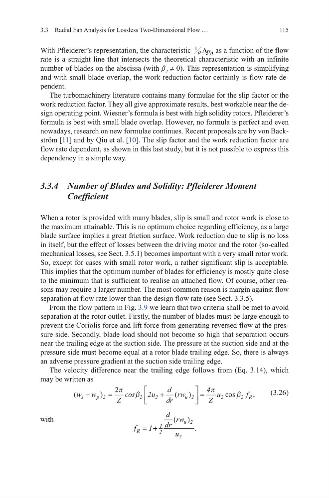
The velocity difference near the trailing edge follows from (Eq. 3.14), which
may be written as
(3.26)
with
(
)
(
)
cos
,
w w
Z
u
d
dr
rw
Z
u
f
s
p
u
R
−
=
+
=
2
2
2
2
2
2
cos
2
4
2π
β
π
β
2
(
)
.
u 2
1
R
2
d rw
dr
f
1
u
= +
3.3 Radial Fan Analysis for Lossless Two-Dimensional Flow …
With Pfleiderer’s representation, the characteristic 1
0
p
r ∆
as a function of the flow
rate is a straight line that intersects the theoretical characteristic with an infinite
number of blades on the abscissa (with β 2 ≠ 0). This representation is simplifying
and with small blade overlap, the work reduction factor certainly is flow rate dependent.
The turbomachinery literature contains many formulae for the slip factor or the
work reduction factor. They all give approximate results, best workable near the design operating point. Wiesner’s formula is best with high solidity rotors. Pfleiderer’s
formula is best with small blade overlap. However, no formula is perfect and even
nowadays, research on new formulae continues. Recent proposals are by von Backström [11] and by Qiu et al. [10]. The slip factor and the work reduction factor are
flow rate dependent, as shown in this last study, but it is not possible to express this
dependency in a simple way.
3.3.4 Number of Blades and Solidity: Pfleiderer Moment
Coefficient
When a rotor is provided with many blades, slip is small and rotor work is close to
the maximum attainable. This is no optimum choice regarding efficiency, as a large
blade surface implies a great friction surface. Work reduction due to slip is no loss
in itself, but the effect of losses between the driving motor and the rotor (so-called
mechanical losses, see Sect. 3.5.1) becomes important with a very small rotor work.
So, except for cases with small rotor work, a rather significant slip is acceptable.
This implies that the optimum number of blades for efficiency is mostly quite close
to the minimum that is sufficient to realise an attached flow. Of course, other reasons may require a larger number. The most common reason is margin against flow
separation at flow rate lower than the design flow rate (see Sect. 3.3.5).
From the flow pattern in Fig. 3.9 we learn that two criteria shall be met to avoid
separation at the rotor outlet. Firstly, the number of blades must be large enough to
prevent the Coriolis force and lift force from generating reversed flow at the pressure side. Secondly, blade load should not become so high that separation occurs
near the trailing edge at the suction side. The pressure at the suction side and at the
pressure side must become equal at a rotor blade trailing edge. So, there is always
an adverse pressure gradient at the suction side trailing edge.
The velocity difference near the trailing edge follows from (Eq. 3.14), which
may be written as
(3.26)
with
(
)
(
)
cos
,
w w
Z
u
d
dr
rw
Z
u
f
s
p
u
R
−
=
+
=
2
2
2
2
2
2
cos
2
4
2π
β
π
β
2
(
)
.
u 2
1
R
2
d rw
dr
f
1
u
= +
3.3 Radial Fan Analysis for Lossless Two-Dimensional Flow …