

88
2 Basic Components
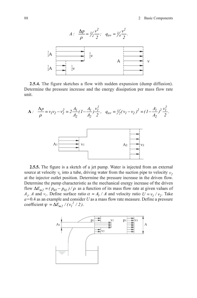
2.5.4. The figure sketches a flow with sudden expansion (dump diffusion).
Determine the pressure increase and the energy dissipation per mass flow rate
unit.
2.5.5. The figure is a sketch of a jet pump. Water is injected from an external
source at velocity v 1 into a tube, driving water from the suction pipe to velocity v 2
at the injector outlet position. Determine the pressure increase in the driven flow.
Determine the pump characteristic as the mechanical energy increase of the driven
flow
m2
03
02
E
( p
p ) /
D
r
=
−
as a function of its mass flow rate at given values of
A 1 , A and v 1 . Define surface ratio
1
A / A
a =
and velocity ratio
1
2
U v / v
=
. Take
a = 0.4 as an example and consider U as a mass flow rate measure. Define a pressure
coefficient
2
m2
1
E / ( v / 2 )
y D
=
.
2
2
1
1
irr
2
4
p
v
v
A :
; q
.
2
2
D
r
=
=
2
2
2
2
2
1
1
1
1
1
1
1 2
2
irr
1
2
2
2
2
2
A
A v
A
v
p
:
v v v
2 ( 1
) , q
( v v ) ( 1
)
.
A
A 2
A
2
D
r
=
− =
−
=
−
= −
A
2 Basic Components
2.5.4. The figure sketches a flow with sudden expansion (dump diffusion).
Determine the pressure increase and the energy dissipation per mass flow rate
unit.
2.5.5. The figure is a sketch of a jet pump. Water is injected from an external
source at velocity v 1 into a tube, driving water from the suction pipe to velocity v 2
at the injector outlet position. Determine the pressure increase in the driven flow.
Determine the pump characteristic as the mechanical energy increase of the driven
flow
m2
03
02
E
( p
p ) /
D
r
=
−
as a function of its mass flow rate at given values of
A 1 , A and v 1 . Define surface ratio
1
A / A
a =
and velocity ratio
1
2
U v / v
=
. Take
a = 0.4 as an example and consider U as a mass flow rate measure. Define a pressure
coefficient
2
m2
1
E / ( v / 2 )
y D
=
.
2
2
1
1
irr
2
4
p
v
v
A :
; q
.
2
2
D
r
=
=
2
2
2
2
2
1
1
1
1
1
1
1 2
2
irr
1
2
2
2
2
2
A
A v
A
v
p
:
v v v
2 ( 1
) , q
( v v ) ( 1
)
.
A
A 2
A
2
D
r
=
− =
−
=
−
= −
A