

44
2 Dynamic Compressive Mechanical Properties of UHPCC
2.4.5 Dynamic Increase Factor
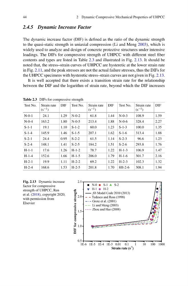
The dynamic increase factor (DIF) is defined as the ratio of the dynamic strength
to the quasi-static strength in uniaxial compression (Li and Meng 2003), which is
widely used to analyze and design of concrete protective structures under intensive
loadings. The DIFs for compressive strength of UHPCC with different steel fiber
contents and types are listed in Table 2.3 and illustrated in Fig. 2.13. It should be
noted that, the stress–strain curves of UHPCC are hysteretic at the lower strain rate
in Fig. 2.11, and the peak stresses are not the actual failure stresses, thus the DIFs for
the UHPCC specimens with hysteretic stress–strain curves are not given in Fig. 2.13.
It is well accepted that there exists a transition strain rate for the relationship
between the DIF and the logarithm of strain rate, beyond which the DIF increases
Table 2.3 DIFs for compressive strength
Test No. Strain rate
(s −1 )
DIF Test No. Strain rate
(s −1 )
DIF Test No. Strain rate
(s −1 )
DIF
N-0-1
24.1
1.29 N-0-2
61.8
1.44 N-0-3
108.9
1.59
N-0-4
163.2
1.80 N-0-5
213.4
1.88 N-0-6
328.4
2.27
S-1-1
19.1
1.10 S-1-2
60.0
1.23 S-1-3
100.0
1.35
S-1-4
145.9
1.46 S-1-5
207.1
1.62 S-1-6
313.4
1.88
S-2-1
24.4
0.95 S-2-2
61.5
1.14 S-2-3
96.6
1.23
S-2-4
148.1
1.41 S-2-5
184.2
1.51 S-2-6
293.8
1.76
H-1-1
17.6
1.26 H-1-2
78.7
1.22 H-1-3
106.9
1.47
H-1-4
152.6
1.66 H-1-5
206.0
1.79 H-1-6
301.7
2.16
H-2-1
19.9
1.11 H-2-2
69.2
1.22 H-2-3
102.3
1.32
H-2-4
168.6
1.53 H-2-5
201.8
1.70 8H-2-6
308.1
1.94
Fig. 2.13 Dynamic increase
factor for compressive
strength of UHPCC, Ren
et al. (2018), copyright 2020,
with permission from
Elsevier
2 Dynamic Compressive Mechanical Properties of UHPCC
2.4.5 Dynamic Increase Factor
The dynamic increase factor (DIF) is defined as the ratio of the dynamic strength
to the quasi-static strength in uniaxial compression (Li and Meng 2003), which is
widely used to analyze and design of concrete protective structures under intensive
loadings. The DIFs for compressive strength of UHPCC with different steel fiber
contents and types are listed in Table 2.3 and illustrated in Fig. 2.13. It should be
noted that, the stress–strain curves of UHPCC are hysteretic at the lower strain rate
in Fig. 2.11, and the peak stresses are not the actual failure stresses, thus the DIFs for
the UHPCC specimens with hysteretic stress–strain curves are not given in Fig. 2.13.
It is well accepted that there exists a transition strain rate for the relationship
between the DIF and the logarithm of strain rate, beyond which the DIF increases
Table 2.3 DIFs for compressive strength
Test No. Strain rate
(s −1 )
DIF Test No. Strain rate
(s −1 )
DIF Test No. Strain rate
(s −1 )
DIF
N-0-1
24.1
1.29 N-0-2
61.8
1.44 N-0-3
108.9
1.59
N-0-4
163.2
1.80 N-0-5
213.4
1.88 N-0-6
328.4
2.27
S-1-1
19.1
1.10 S-1-2
60.0
1.23 S-1-3
100.0
1.35
S-1-4
145.9
1.46 S-1-5
207.1
1.62 S-1-6
313.4
1.88
S-2-1
24.4
0.95 S-2-2
61.5
1.14 S-2-3
96.6
1.23
S-2-4
148.1
1.41 S-2-5
184.2
1.51 S-2-6
293.8
1.76
H-1-1
17.6
1.26 H-1-2
78.7
1.22 H-1-3
106.9
1.47
H-1-4
152.6
1.66 H-1-5
206.0
1.79 H-1-6
301.7
2.16
H-2-1
19.9
1.11 H-2-2
69.2
1.22 H-2-3
102.3
1.32
H-2-4
168.6
1.53 H-2-5
201.8
1.70 8H-2-6
308.1
1.94
Fig. 2.13 Dynamic increase
factor for compressive
strength of UHPCC, Ren
et al. (2018), copyright 2020,
with permission from
Elsevier