

436
13 Experimental and Numerical Studies on Dynamic Behavior …
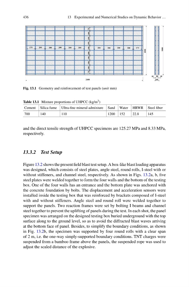
Fig. 13.1 Geometry and reinforcement of test panels (unit mm)
Table 13.1 Mixture proportions of UHPCC (kg/m 3 )
Cement Silica fume Ultra-fine mineral admixture Sand Water HRWR Steel fiber
700
140
110
1200 152
22.8
145
and the direct tensile strength of UHPCC specimens are 125.27 MPa and 8.33 MPa,
respectively.
13.3.2 Test Setup
Figure 13.2 shows the present field blast test setup. A box-like blast loading apparatus
was designed, which consists of steel plates, angle steel, round rolls, I-steel with or
without stiffeners, and channel steel, respectively. As shown in Figs. 13.2a, b, five
steel plates were welded together to form the four walls and the bottom of the testing
box. One of the four walls has an entrance and the bottom plate was anchored with
the concrete foundation by bolts. The displacement and acceleration sensors were
installed inside the testing box that was reinforced by brackets composed of I-steel
with and without stiffeners. Angle steel and round roll were welded together to
support the panels. Two reaction frames were set by bolting I beams and channel
steel together to prevent the uplifting of panels during the test. In each shot, the panel
specimen was arranged on the designed testing box buried underground with the top
surface along to the ground level, so as to avoid the diffracted blast waves arriving
at the bottom face of panel. Besides, to simplify the boundary conditions, as shown
in Fig. 13.2b, the specimen was supported by four round rolls with a clear span
of 2 m, i.e. the one-way simply-supported boundary conditions. TNT charges were
suspended from a bamboo frame above the panels, the suspended rope was used to
adjust the scaled distance of the explosive.
13 Experimental and Numerical Studies on Dynamic Behavior …
Fig. 13.1 Geometry and reinforcement of test panels (unit mm)
Table 13.1 Mixture proportions of UHPCC (kg/m 3 )
Cement Silica fume Ultra-fine mineral admixture Sand Water HRWR Steel fiber
700
140
110
1200 152
22.8
145
and the direct tensile strength of UHPCC specimens are 125.27 MPa and 8.33 MPa,
respectively.
13.3.2 Test Setup
Figure 13.2 shows the present field blast test setup. A box-like blast loading apparatus
was designed, which consists of steel plates, angle steel, round rolls, I-steel with or
without stiffeners, and channel steel, respectively. As shown in Figs. 13.2a, b, five
steel plates were welded together to form the four walls and the bottom of the testing
box. One of the four walls has an entrance and the bottom plate was anchored with
the concrete foundation by bolts. The displacement and acceleration sensors were
installed inside the testing box that was reinforced by brackets composed of I-steel
with and without stiffeners. Angle steel and round roll were welded together to
support the panels. Two reaction frames were set by bolting I beams and channel
steel together to prevent the uplifting of panels during the test. In each shot, the panel
specimen was arranged on the designed testing box buried underground with the top
surface along to the ground level, so as to avoid the diffracted blast waves arriving
at the bottom face of panel. Besides, to simplify the boundary conditions, as shown
in Fig. 13.2b, the specimen was supported by four round rolls with a clear span
of 2 m, i.e. the one-way simply-supported boundary conditions. TNT charges were
suspended from a bamboo frame above the panels, the suspended rope was used to
adjust the scaled distance of the explosive.