

12.1 Introduction
399
were mainly focused on the near or far range (Z > 0.1 m/kg
1/3 ) detonation; (iii) The
residual seismic resistance (RSR) of structural members under service in the seismic
zone after blast loadings is also very important, while the related work is scarce. For
instance, only the seismic capacities of CFST column and CFST column-to-beam
joint were studied in (Elremaily and Azizinamini 2002; Liao et al. 2014; Ge and
Usami 1996; Han et al. 2009), and the residual seismic performance of the structural
members after environmental corrosion or exposure to fire were concerned in (Ma
et al. 2018; Rajput and Sharma, 2018; Mosherf et al. 2017; Chung et al. 2008).
In this chapter, the experimental study on the RSR of UHPCC-FST column after
contact explosion was conducted. Firstly, six UHPCC-FST columns were fabricated,
and four of them were tested under the contact explosion with the TNT charge weight
varying from 1 to 3 kg, from which the local deformations and failure modes of
columns were examined. Secondly, the seismic resistance of the intact and blastdamaged columns was evaluated through the low-frequency cyclic loading test. The
failure modes of the columns under combined action of contact detonation and cyclic
loading were obtained. The seismic capacities of the specimens, such as load-carrying
capacity, stiffness, and energy consumption, were discussed based on the hysteresis
behavior of the UHPCC-FST columns. Finally, the composite damage index was
proposed to evaluate the RSR of UHPCC-FST column after blast.
12.2 UHPCC-FST Specimens
12.2.1 Steel Tube
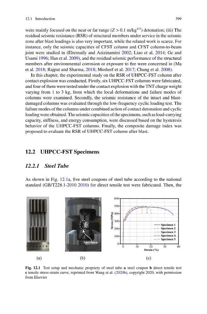
As shown in Fig. 12.1a, five steel coupons of steel tube according to the national
standard (GB/T228.1-2010 2010) for direct tensile test were fabricated. Then, the
Specimen
0
1 0
2 0
3 0
4 0
0
100
200
300
400
500
600
Specimen 1
Specimen 2
Specimen 3
Specimen 4
Specimen 5
Stress (MPa)
Strain (%)
(a)
(b)
(c)
Fig. 12.1 Test setup and mechanic propriety of steel tube a steel coupon b direct tensile test
c tensile stress-strain curve, reprinted from Wang et al. (2020b), copyright 2020, with permission
from Elsevier
399
were mainly focused on the near or far range (Z > 0.1 m/kg
1/3 ) detonation; (iii) The
residual seismic resistance (RSR) of structural members under service in the seismic
zone after blast loadings is also very important, while the related work is scarce. For
instance, only the seismic capacities of CFST column and CFST column-to-beam
joint were studied in (Elremaily and Azizinamini 2002; Liao et al. 2014; Ge and
Usami 1996; Han et al. 2009), and the residual seismic performance of the structural
members after environmental corrosion or exposure to fire were concerned in (Ma
et al. 2018; Rajput and Sharma, 2018; Mosherf et al. 2017; Chung et al. 2008).
In this chapter, the experimental study on the RSR of UHPCC-FST column after
contact explosion was conducted. Firstly, six UHPCC-FST columns were fabricated,
and four of them were tested under the contact explosion with the TNT charge weight
varying from 1 to 3 kg, from which the local deformations and failure modes of
columns were examined. Secondly, the seismic resistance of the intact and blastdamaged columns was evaluated through the low-frequency cyclic loading test. The
failure modes of the columns under combined action of contact detonation and cyclic
loading were obtained. The seismic capacities of the specimens, such as load-carrying
capacity, stiffness, and energy consumption, were discussed based on the hysteresis
behavior of the UHPCC-FST columns. Finally, the composite damage index was
proposed to evaluate the RSR of UHPCC-FST column after blast.
12.2 UHPCC-FST Specimens
12.2.1 Steel Tube
As shown in Fig. 12.1a, five steel coupons of steel tube according to the national
standard (GB/T228.1-2010 2010) for direct tensile test were fabricated. Then, the
Specimen
0
1 0
2 0
3 0
4 0
0
100
200
300
400
500
600
Specimen 1
Specimen 2
Specimen 3
Specimen 4
Specimen 5
Stress (MPa)
Strain (%)
(a)
(b)
(c)
Fig. 12.1 Test setup and mechanic propriety of steel tube a steel coupon b direct tensile test
c tensile stress-strain curve, reprinted from Wang et al. (2020b), copyright 2020, with permission
from Elsevier