

380
11 Experimental and Numerical Study of UHPCC-FST Columns …
Table 11.4 Material
parameters and EOS for air
and TNT (Cheng et al. 2013)
Air
TNT
Initial
density, ρ 0
1.29 kg/m 3
Initial density,
ρ 0
1630 kg/m 3
Pressure
cut-off
0
Detonation
velocity
6930 m/s
Dynamic
viscosity
0
CJ pressure P 21 GPa
Constant
C 0 -C 3
0
Constant A
371.2 GPa
Constant C 4 0.4
Constant B
3.23 GPa
Constant C 5 0.4
Constant R 1
4.15
Constant C 6 0
Constant R 2
0.95
Initial
energy, E 0
2.5 × 10 9
J/m 3
Constant ω
0.3
Initial energy,
E 0
7 × 10 9 J/m 3
11.3.1.3 Air and Explosive
The air is modelled with the *MAT_NULL material model by combining the linear
polynomial Equation of State (EOS) given in Eq. (11.4) (LSTC 2017).
P = C 0 + C 1 μ + C 2 μ
2
+ C 3 μ
3
+
C 4 + C 5 μ + C 6 μ
2
E 0
(11.4)
where P is pressure, C 0 ~C 6 are polynomial equation coefficients, E 0 is the internal
energy per unit volume. μ = ρ/ρ 0 − 1 represents the volumetric strain, where ρ
and ρ 0 are the current and initial densities, respectively. The adopted parameters of
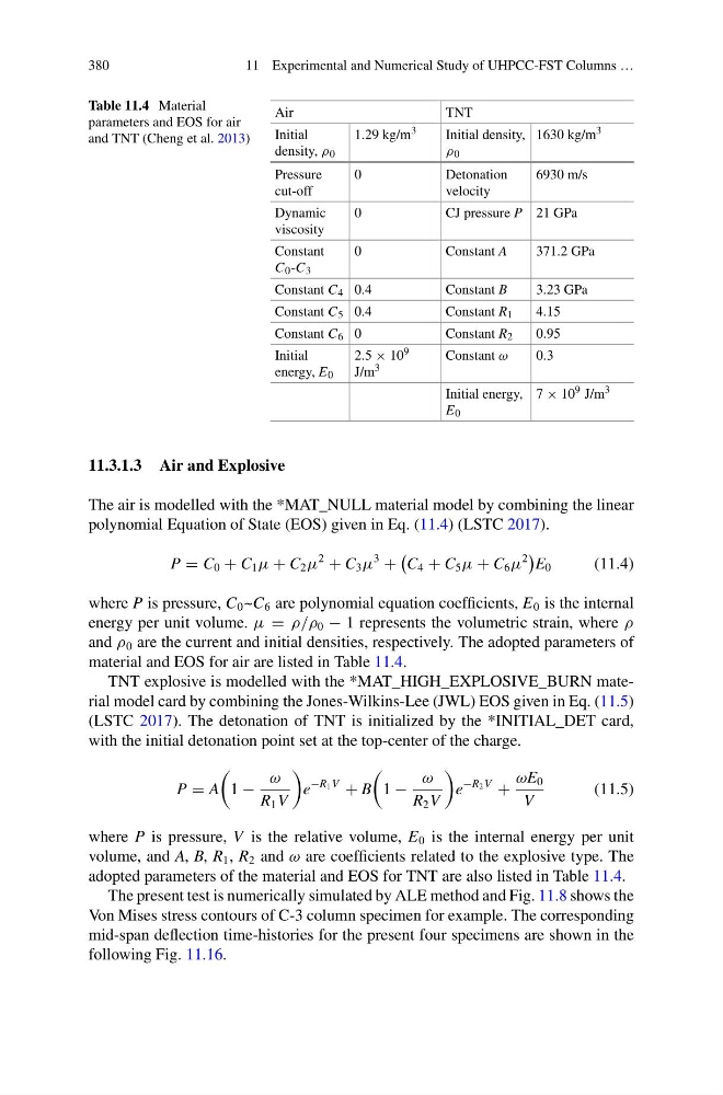
material and EOS for air are listed in Table 11.4.
TNT explosive is modelled with the *MAT_HIGH_EXPLOSIVE_BURN material model card by combining the Jones-Wilkins-Lee (JWL) EOS given in Eq. (11.5)
(LSTC 2017). The detonation of TNT is initialized by the *INITIAL_DET card,
with the initial detonation point set at the top-center of the charge.
P = A
1 −
ω
R 1 V
e
−R 1 V
+ B
1 −
ω
R 2 V
e
−R 2 V
+
ωE 0
V
(11.5)
where P is pressure, V is the relative volume, E 0 is the internal energy per unit
volume, and A, B, R 1 , R 2 and ω are coefficients related to the explosive type. The
adopted parameters of the material and EOS for TNT are also listed in Table 11.4.
The present test is numerically simulated by ALE method and Fig. 11.8 shows the
Von Mises stress contours of C-3 column specimen for example. The corresponding
mid-span deflection time-histories for the present four specimens are shown in the
following Fig. 11.16.
11 Experimental and Numerical Study of UHPCC-FST Columns …
Table 11.4 Material
parameters and EOS for air
and TNT (Cheng et al. 2013)
Air
TNT
Initial
density, ρ 0
1.29 kg/m 3
Initial density,
ρ 0
1630 kg/m 3
Pressure
cut-off
0
Detonation
velocity
6930 m/s
Dynamic
viscosity
0
CJ pressure P 21 GPa
Constant
C 0 -C 3
0
Constant A
371.2 GPa
Constant C 4 0.4
Constant B
3.23 GPa
Constant C 5 0.4
Constant R 1
4.15
Constant C 6 0
Constant R 2
0.95
Initial
energy, E 0
2.5 × 10 9
J/m 3
Constant ω
0.3
Initial energy,
E 0
7 × 10 9 J/m 3
11.3.1.3 Air and Explosive
The air is modelled with the *MAT_NULL material model by combining the linear
polynomial Equation of State (EOS) given in Eq. (11.4) (LSTC 2017).
P = C 0 + C 1 μ + C 2 μ
2
+ C 3 μ
3
+
C 4 + C 5 μ + C 6 μ
2
E 0
(11.4)
where P is pressure, C 0 ~C 6 are polynomial equation coefficients, E 0 is the internal
energy per unit volume. μ = ρ/ρ 0 − 1 represents the volumetric strain, where ρ
and ρ 0 are the current and initial densities, respectively. The adopted parameters of
material and EOS for air are listed in Table 11.4.
TNT explosive is modelled with the *MAT_HIGH_EXPLOSIVE_BURN material model card by combining the Jones-Wilkins-Lee (JWL) EOS given in Eq. (11.5)
(LSTC 2017). The detonation of TNT is initialized by the *INITIAL_DET card,
with the initial detonation point set at the top-center of the charge.
P = A
1 −
ω
R 1 V
e
−R 1 V
+ B
1 −
ω
R 2 V
e
−R 2 V
+
ωE 0
V
(11.5)
where P is pressure, V is the relative volume, E 0 is the internal energy per unit
volume, and A, B, R 1 , R 2 and ω are coefficients related to the explosive type. The
adopted parameters of the material and EOS for TNT are also listed in Table 11.4.
The present test is numerically simulated by ALE method and Fig. 11.8 shows the
Von Mises stress contours of C-3 column specimen for example. The corresponding
mid-span deflection time-histories for the present four specimens are shown in the
following Fig. 11.16.