

10.7 Comparisons with Test Data
347
250
Original contour line
25
(a)
R1
R2
R3
(b)
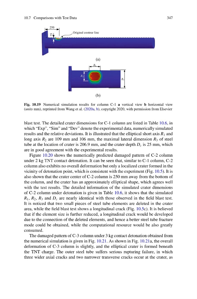
Fig. 10.19 Numerical simulation results for column C-1 a vertical view b horizontal view
(units mm), reprinted from Wang et al. (2020a, b), copyright 2020, with permission from Elsevier
blast test. The detailed crater dimensions for C-1 column are listed in Table 10.6, in
which “Exp”, “Sim” and “Dev” denote the experimental data, numerically simulated
results and the relative deviations. It is illustrated that the elliptical short axis R 1 and
long axis R 2 are 109 mm and 106 mm, the maximal lateral dimension R 3 of steel
tube at the location of crater is 206.9 mm, and the crater depth D c is 25 mm, which
are in good agreement with the experimental results.
Figure 10.20 shows the numerically predicted damaged pattern of C-2 column
under 2 kg TNT contact detonation. It can be seen that, similar to C-1 column, C-2
column also exhibits no overall deformation but only a localized crater formed in the
vicinity of detonation point, which is consistent with the experiment (Fig. 10.5). It is
also shown that the crater center of C-2 column is 250 mm away from the bottom of
the column, and the crater has an approximately elliptical shape, which agrees well
with the test results. The detailed information of the simulated crater dimensions
of C-2 column under detonation is given in Table 10.6, it shows that the simulated
R 1 , R 2 , R 3 and D c are nearly identical with those observed in the field blast test.
It is noticed that two small pieces of steel tube elements are deleted in the crater
area, while the field blast test shows a longitudinal crack (Fig. 10.5c). It is believed
that if the element size is further reduced, a longitudinal crack would be developed
due to the connection of the deleted elements, and hence a better steel tube fracture
mode could be obtained, while the computational resource would be also greatly
consumed.
The damaged pattern of C-3 column under 3 kg contact detonation obtained from
the numerical simulation is given in Fig. 10.21. As shown in Fig. 10.21a, the overall
deformation of C-3 column is slightly, and the elliptical crater is formed beneath
the TNT charge. The outer steel tube suffers serious rupturing failure, in which
three wider axial cracks and two narrower transverse cracks occur at the crater, as
347
250
Original contour line
25
(a)
R1
R2
R3
(b)
Fig. 10.19 Numerical simulation results for column C-1 a vertical view b horizontal view
(units mm), reprinted from Wang et al. (2020a, b), copyright 2020, with permission from Elsevier
blast test. The detailed crater dimensions for C-1 column are listed in Table 10.6, in
which “Exp”, “Sim” and “Dev” denote the experimental data, numerically simulated
results and the relative deviations. It is illustrated that the elliptical short axis R 1 and
long axis R 2 are 109 mm and 106 mm, the maximal lateral dimension R 3 of steel
tube at the location of crater is 206.9 mm, and the crater depth D c is 25 mm, which
are in good agreement with the experimental results.
Figure 10.20 shows the numerically predicted damaged pattern of C-2 column
under 2 kg TNT contact detonation. It can be seen that, similar to C-1 column, C-2
column also exhibits no overall deformation but only a localized crater formed in the
vicinity of detonation point, which is consistent with the experiment (Fig. 10.5). It is
also shown that the crater center of C-2 column is 250 mm away from the bottom of
the column, and the crater has an approximately elliptical shape, which agrees well
with the test results. The detailed information of the simulated crater dimensions
of C-2 column under detonation is given in Table 10.6, it shows that the simulated
R 1 , R 2 , R 3 and D c are nearly identical with those observed in the field blast test.
It is noticed that two small pieces of steel tube elements are deleted in the crater
area, while the field blast test shows a longitudinal crack (Fig. 10.5c). It is believed
that if the element size is further reduced, a longitudinal crack would be developed
due to the connection of the deleted elements, and hence a better steel tube fracture
mode could be obtained, while the computational resource would be also greatly
consumed.
The damaged pattern of C-3 column under 3 kg contact detonation obtained from
the numerical simulation is given in Fig. 10.21. As shown in Fig. 10.21a, the overall
deformation of C-3 column is slightly, and the elliptical crater is formed beneath
the TNT charge. The outer steel tube suffers serious rupturing failure, in which
three wider axial cracks and two narrower transverse cracks occur at the crater, as