

142
6 Mathematical Models of Micro- and Nano-cylindrical Panels in Temperature Field
W =
L
0
f u + qw + cθ y
dx +
¯
N u + ¯
Qw + ¯
Mϕ + α ¯
P
∂w
∂ x
x=L
x=0
, (6.36)
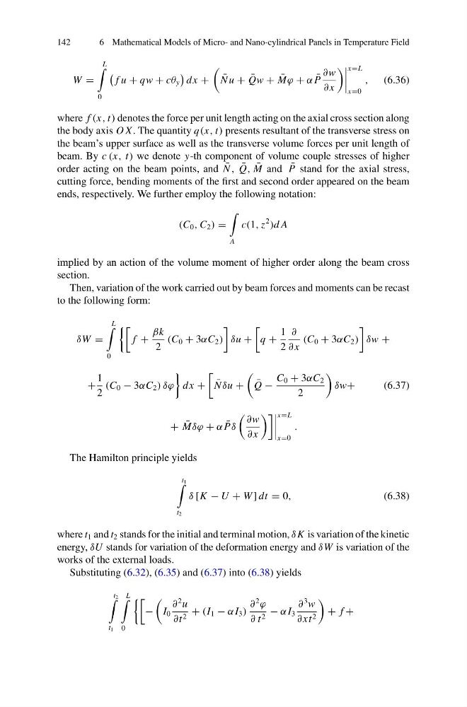
where f (x, t) denotes the force per unit length acting on the axial cross section along
the body axis O X. The quantity q(x, t) presents resultant of the transverse stress on
the beam’s upper surface as well as the transverse volume forces per unit length of
beam. By c (x, t) we denote y-th component of volume couple stresses of higher
order acting on the beam points, and ¯
N , ¯
Q, ¯
M and ¯
P stand for the axial stress,
cutting force, bending moments of the first and second order appeared on the beam
ends, respectively. We further employ the following notation:
(C 0 , C 2 ) =
A
c(1, z
2
)d A
implied by an action of the volume moment of higher order along the beam cross
section.
Then, variation of the work carried out by beam forces and moments can be recast
to the following form:
δW =
L
0
f +
βk
2
(C 0 + 3αC 2 )
δu +
q +
1
2
∂
∂ x
(C 0 + 3αC 2 )
δw +
+
1
2
(C 0 − 3αC 2 ) δϕ
dx +
¯
N δu +
¯
Q −
C 0 + 3αC 2
2
δw+
(6.37)
+ ¯
Mδϕ + α ¯
Pδ
∂w
∂ x
x=L
x=0
.
The Hamilton principle yields
t 1
t 2
δ [K − U + W ] dt = 0,
(6.38)
where t 1 and t 2 stands for the initial and terminal motion, δ K is variation of the kinetic
energy, δU stands for variation of the deformation energy and δW is variation of the
works of the external loads.
Substituting (6.32), (6.35) and (6.37) into (6.38) yields
t 2
t 1
L
0
−
I 0
∂
2 u
∂t 2 + (I 1 − α I 3 )
∂
2
ϕ
∂ t 2 − α I 3
∂
3 w
∂ xt 2
+ f +
6 Mathematical Models of Micro- and Nano-cylindrical Panels in Temperature Field
W =
L
0
f u + qw + cθ y
dx +
¯
N u + ¯
Qw + ¯
Mϕ + α ¯
P
∂w
∂ x
x=L
x=0
, (6.36)
where f (x, t) denotes the force per unit length acting on the axial cross section along
the body axis O X. The quantity q(x, t) presents resultant of the transverse stress on
the beam’s upper surface as well as the transverse volume forces per unit length of
beam. By c (x, t) we denote y-th component of volume couple stresses of higher
order acting on the beam points, and ¯
N , ¯
Q, ¯
M and ¯
P stand for the axial stress,
cutting force, bending moments of the first and second order appeared on the beam
ends, respectively. We further employ the following notation:
(C 0 , C 2 ) =
A
c(1, z
2
)d A
implied by an action of the volume moment of higher order along the beam cross
section.
Then, variation of the work carried out by beam forces and moments can be recast
to the following form:
δW =
L
0
f +
βk
2
(C 0 + 3αC 2 )
δu +
q +
1
2
∂
∂ x
(C 0 + 3αC 2 )
δw +
+
1
2
(C 0 − 3αC 2 ) δϕ
dx +
¯
N δu +
¯
Q −
C 0 + 3αC 2
2
δw+
(6.37)
+ ¯
Mδϕ + α ¯
Pδ
∂w
∂ x
x=L
x=0
.
The Hamilton principle yields
t 1
t 2
δ [K − U + W ] dt = 0,
(6.38)
where t 1 and t 2 stands for the initial and terminal motion, δ K is variation of the kinetic
energy, δU stands for variation of the deformation energy and δW is variation of the
works of the external loads.
Substituting (6.32), (6.35) and (6.37) into (6.38) yields
t 2
t 1
L
0
−
I 0
∂
2 u
∂t 2 + (I 1 − α I 3 )
∂
2
ϕ
∂ t 2 − α I 3
∂
3 w
∂ xt 2
+ f +