

48
N. K. Jha et al.
Fig. 3 FSW fixture
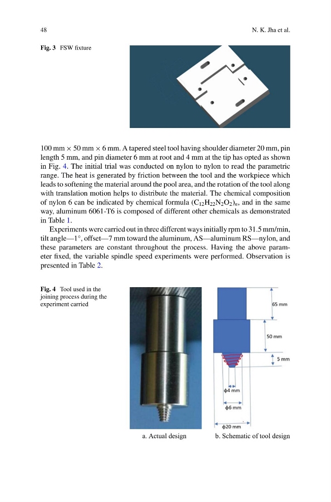
100 mm × 50 mm × 6 mm. A tapered steel tool having shoulder diameter 20 mm, pin
length 5 mm, and pin diameter 6 mm at root and 4 mm at the tip has opted as shown
in Fig. 4. The initial trial was conducted on nylon to nylon to read the parametric
range. The heat is generated by friction between the tool and the workpiece which
leads to softening the material around the pool area, and the rotation of the tool along
with translation motion helps to distribute the material. The chemical composition
of nylon 6 can be indicated by chemical formula (C 12 H 22 N 2 O 2 ) n , and in the same
way, aluminum 6061-T6 is composed of different other chemicals as demonstrated
in Table 1.
Experiments were carried out in three different ways initially rpm to 31.5 mm/min,
tilt angle—1°, offset—7 mm toward the aluminum, AS—aluminum RS—nylon, and
these parameters are constant throughout the process. Having the above parameter fixed, the variable spindle speed experiments were performed. Observation is
presented in Table 2.
Fig. 4 Tool used in the
joining process during the
experiment carried
a. Actual design
b. Schematic of tool design
N. K. Jha et al.
Fig. 3 FSW fixture
100 mm × 50 mm × 6 mm. A tapered steel tool having shoulder diameter 20 mm, pin
length 5 mm, and pin diameter 6 mm at root and 4 mm at the tip has opted as shown
in Fig. 4. The initial trial was conducted on nylon to nylon to read the parametric
range. The heat is generated by friction between the tool and the workpiece which
leads to softening the material around the pool area, and the rotation of the tool along
with translation motion helps to distribute the material. The chemical composition
of nylon 6 can be indicated by chemical formula (C 12 H 22 N 2 O 2 ) n , and in the same
way, aluminum 6061-T6 is composed of different other chemicals as demonstrated
in Table 1.
Experiments were carried out in three different ways initially rpm to 31.5 mm/min,
tilt angle—1°, offset—7 mm toward the aluminum, AS—aluminum RS—nylon, and
these parameters are constant throughout the process. Having the above parameter fixed, the variable spindle speed experiments were performed. Observation is
presented in Table 2.
Fig. 4 Tool used in the
joining process during the
experiment carried
a. Actual design
b. Schematic of tool design