

Structural Analysis, Design, and Implementation of Safety …
447
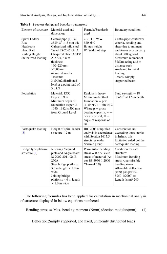
Table 1 Structure design and boundary parameters
Element of structure Material used and
dimension
Formula/Standards
used
Boundary condition
Spiral Ladder
Rise
Headroom
Hand Rail
Railing Height
Stairs tread loading
Central pipe [1]: IS
3589, 8 × 8 mm thk
Galvanized mild steel
Tread: IS-2062 Gr. A
Chequred plate: ASTM
A-5725, 6 mm
thickness
160–220 mm
>2000 mm
42 mm diameter
1100 mm
3 kN/m2 distributed
load or a point load of
3.0 kN
2 × H + W =
580–640
H: step height
W: Width of step
Centre pipe: cantilever
criteria, bending and
shear due to moment
and forces acts on carry
about 300 kg load
Maximum moment of
3 kNm acting at 3 m
distance each
Analyzed for wind
loading
Treads: Simply
supported beam
Foundation
Material: RCC
Depth: 0.9 m
Minimum depth of
foundation as per IS
1080–1982 is 500 mm
from Ground Level
Rankine’s theory
Minimum depth of
foundation = p/w
(1-sin /1 + sin ) 2
Where p = gross
bearing capacity, w =
density of soil, =
angle of response of
soil
Sand strength = 18
Ton/m 2 at 1.5 m depth
Earthquake loading
[3]
Height of spiral ladder
structure: 12 m
IBC 2003 simplified
analysis in accordance
with Section 1617.5
structures under
Seismic group 1
Construction not
exceeding three stories
in height, this
limitation ruled out the
earthquake loading
Bridge type plaform
structure [2]
I-Beam, Chequred
plate and Angle beam:
IS 2002-2011 Gr. E
250A
Start bridge platform:
3.6 m length × 1.0 m
wide
Joining bridge
platform: 4.6 m length
× 1.0 m wide
Permissible bending
stress = 0.8 × Yield
stress of material (As
per BS 5950-1:2000
Clause 4.3.8)
Condition for safe
structure:
Maximum Bending
stress < permissible
bending stress
Allowable deflection
(mm) [As per BS
5950-1:2000] =
Length (mm)/ 240
The following formulas has been applied for calculation in mechanical analysis
of structure displayed in below equations numbered
Bending stress = Max. bending moment (Nmm)/Section modulus(mm) (1)
Deflection(Simply supported, end fixed, uniformly distributed load)
447
Table 1 Structure design and boundary parameters
Element of structure Material used and
dimension
Formula/Standards
used
Boundary condition
Spiral Ladder
Rise
Headroom
Hand Rail
Railing Height
Stairs tread loading
Central pipe [1]: IS
3589, 8 × 8 mm thk
Galvanized mild steel
Tread: IS-2062 Gr. A
Chequred plate: ASTM
A-5725, 6 mm
thickness
160–220 mm
>2000 mm
42 mm diameter
1100 mm
3 kN/m2 distributed
load or a point load of
3.0 kN
2 × H + W =
580–640
H: step height
W: Width of step
Centre pipe: cantilever
criteria, bending and
shear due to moment
and forces acts on carry
about 300 kg load
Maximum moment of
3 kNm acting at 3 m
distance each
Analyzed for wind
loading
Treads: Simply
supported beam
Foundation
Material: RCC
Depth: 0.9 m
Minimum depth of
foundation as per IS
1080–1982 is 500 mm
from Ground Level
Rankine’s theory
Minimum depth of
foundation = p/w
(1-sin /1 + sin ) 2
Where p = gross
bearing capacity, w =
density of soil, =
angle of response of
soil
Sand strength = 18
Ton/m 2 at 1.5 m depth
Earthquake loading
[3]
Height of spiral ladder
structure: 12 m
IBC 2003 simplified
analysis in accordance
with Section 1617.5
structures under
Seismic group 1
Construction not
exceeding three stories
in height, this
limitation ruled out the
earthquake loading
Bridge type plaform
structure [2]
I-Beam, Chequred
plate and Angle beam:
IS 2002-2011 Gr. E
250A
Start bridge platform:
3.6 m length × 1.0 m
wide
Joining bridge
platform: 4.6 m length
× 1.0 m wide
Permissible bending
stress = 0.8 × Yield
stress of material (As
per BS 5950-1:2000
Clause 4.3.8)
Condition for safe
structure:
Maximum Bending
stress < permissible
bending stress
Allowable deflection
(mm) [As per BS
5950-1:2000] =
Length (mm)/ 240
The following formulas has been applied for calculation in mechanical analysis
of structure displayed in below equations numbered
Bending stress = Max. bending moment (Nmm)/Section modulus(mm) (1)
Deflection(Simply supported, end fixed, uniformly distributed load)