

A Study of Linear Fresnel Solar Collector Reflector …
355
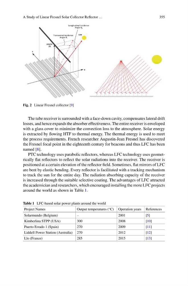
Fig. 2 Linear Fresnel collector [9]
The tube receiver is surrounded with a face-down cavity, compensates lateral drift
losses, and hence expands the absorber effectiveness. The entire receiver is enveloped
with a glass cover to minimize the convection loss to the atmosphere. Solar energy
is extracted by flowing HTF to thermal energy. The thermal energy is used to meet
the process requirements. French researcher Augustin-Jean Fresnel has discovered
the Fresnel focal point in the eighteenth century for beacons and thus LFC has been
named [8].
PTC technology uses parabolic reflectors, whereas LFC technology uses geometrically flat reflectors to reflect the solar radiations into the receiver. The receiver is
positioned at a certain elevation of the reflector field. Sometimes, flat mirrors of LFC
are bent by elastic bending. Every reflector is facilitated with a tracking mechanism
to track the sun for the entire day. The radiation absorbing capacity of the receiver
is increased through the suitable selective coating. The advantages of LFC attracted
the academician and researchers, which encouraged installing the more LFC projects
around the world as shown in Table 1.
Table 1 LFC-based solar power plants around the world
Project Names
Output temperatures (°C) Operation years References
Solarmundo (Belgium)
–
2001
[5]
Kimberlina STPP (USA)
300
2008
[10]
Puerto Errado 1 (Spain)
270
2009
[11]
Liddell Power Station (Australia) 270
2012
[12]
Llo (France)
285
2015
[13]
355
Fig. 2 Linear Fresnel collector [9]
The tube receiver is surrounded with a face-down cavity, compensates lateral drift
losses, and hence expands the absorber effectiveness. The entire receiver is enveloped
with a glass cover to minimize the convection loss to the atmosphere. Solar energy
is extracted by flowing HTF to thermal energy. The thermal energy is used to meet
the process requirements. French researcher Augustin-Jean Fresnel has discovered
the Fresnel focal point in the eighteenth century for beacons and thus LFC has been
named [8].
PTC technology uses parabolic reflectors, whereas LFC technology uses geometrically flat reflectors to reflect the solar radiations into the receiver. The receiver is
positioned at a certain elevation of the reflector field. Sometimes, flat mirrors of LFC
are bent by elastic bending. Every reflector is facilitated with a tracking mechanism
to track the sun for the entire day. The radiation absorbing capacity of the receiver
is increased through the suitable selective coating. The advantages of LFC attracted
the academician and researchers, which encouraged installing the more LFC projects
around the world as shown in Table 1.
Table 1 LFC-based solar power plants around the world
Project Names
Output temperatures (°C) Operation years References
Solarmundo (Belgium)
–
2001
[5]
Kimberlina STPP (USA)
300
2008
[10]
Puerto Errado 1 (Spain)
270
2009
[11]
Liddell Power Station (Australia) 270
2012
[12]
Llo (France)
285
2015
[13]