

254
K. Mekrisuh et al.
a TES system to avoid incomplete utility of the storage material or the system. To
further improve the performance of TES system by achieving the same total melting
time of PCM in each zone, case 3 and case 4 are studied. As observed from the
previous section that the inner zone of case 1 and upper zone of case 2 melt faster.
Therefore, the outer zone of case 3 and lower zone of case 4 are filled with only 15%
of the total mass of PCM by suitable placing of the partitions. This is done considering
that the total melting time of PCM is dependent on the PCM mass proportion in each
zone and to achieve same melting time for each zone of the TES system.
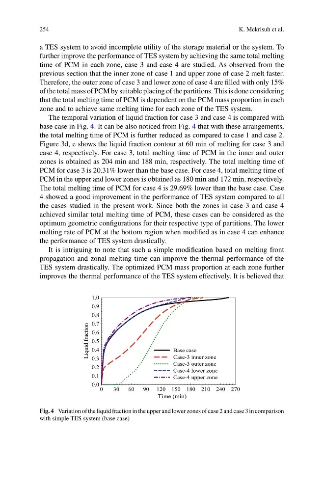
The temporal variation of liquid fraction for case 3 and case 4 is compared with
base case in Fig. 4. It can be also noticed from Fig. 4 that with these arrangements,
the total melting time of PCM is further reduced as compared to case 1 and case 2.
Figure 3d, e shows the liquid fraction contour at 60 min of melting for case 3 and
case 4, respectively. For case 3, total melting time of PCM in the inner and outer
zones is obtained as 204 min and 188 min, respectively. The total melting time of
PCM for case 3 is 20.31% lower than the base case. For case 4, total melting time of
PCM in the upper and lower zones is obtained as 180 min and 172 min, respectively.
The total melting time of PCM for case 4 is 29.69% lower than the base case. Case
4 showed a good improvement in the performance of TES system compared to all
the cases studied in the present work. Since both the zones in case 3 and case 4
achieved similar total melting time of PCM, these cases can be considered as the
optimum geometric configurations for their respective type of partitions. The lower
melting rate of PCM at the bottom region when modified as in case 4 can enhance
the performance of TES system drastically.
It is intriguing to note that such a simple modification based on melting front
propagation and zonal melting time can improve the thermal performance of the
TES system drastically. The optimized PCM mass proportion at each zone further
improves the thermal performance of the TES system effectively. It is believed that
Time (min)
0
30
60
90 120 150 180 210 240 270
Liquid fraction
0.0
0.1
0.2
0.3
0.4
0.5
0.6
0.7
0.8
0.9
1.0
Base case
Case-3 inner zone
Case-3 outer zone
Case-4 lower zone
Case-4 upper zone
Fig. 4 Variation of the liquid fraction in the upper and lower zones of case 2 and case 3 in comparison
with simple TES system (base case)
K. Mekrisuh et al.
a TES system to avoid incomplete utility of the storage material or the system. To
further improve the performance of TES system by achieving the same total melting
time of PCM in each zone, case 3 and case 4 are studied. As observed from the
previous section that the inner zone of case 1 and upper zone of case 2 melt faster.
Therefore, the outer zone of case 3 and lower zone of case 4 are filled with only 15%
of the total mass of PCM by suitable placing of the partitions. This is done considering
that the total melting time of PCM is dependent on the PCM mass proportion in each
zone and to achieve same melting time for each zone of the TES system.
The temporal variation of liquid fraction for case 3 and case 4 is compared with
base case in Fig. 4. It can be also noticed from Fig. 4 that with these arrangements,
the total melting time of PCM is further reduced as compared to case 1 and case 2.
Figure 3d, e shows the liquid fraction contour at 60 min of melting for case 3 and
case 4, respectively. For case 3, total melting time of PCM in the inner and outer
zones is obtained as 204 min and 188 min, respectively. The total melting time of
PCM for case 3 is 20.31% lower than the base case. For case 4, total melting time of
PCM in the upper and lower zones is obtained as 180 min and 172 min, respectively.
The total melting time of PCM for case 4 is 29.69% lower than the base case. Case
4 showed a good improvement in the performance of TES system compared to all
the cases studied in the present work. Since both the zones in case 3 and case 4
achieved similar total melting time of PCM, these cases can be considered as the
optimum geometric configurations for their respective type of partitions. The lower
melting rate of PCM at the bottom region when modified as in case 4 can enhance
the performance of TES system drastically.
It is intriguing to note that such a simple modification based on melting front
propagation and zonal melting time can improve the thermal performance of the
TES system drastically. The optimized PCM mass proportion at each zone further
improves the thermal performance of the TES system effectively. It is believed that
Time (min)
0
30
60
90 120 150 180 210 240 270
Liquid fraction
0.0
0.1
0.2
0.3
0.4
0.5
0.6
0.7
0.8
0.9
1.0
Base case
Case-3 inner zone
Case-3 outer zone
Case-4 lower zone
Case-4 upper zone
Fig. 4 Variation of the liquid fraction in the upper and lower zones of case 2 and case 3 in comparison
with simple TES system (base case)