

136
D. K. Sharma et al.
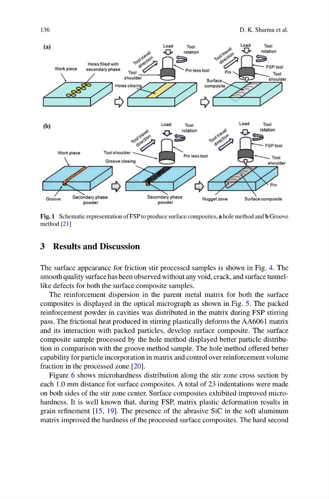
Fig. 1 Schematic representation of FSP to produce surface composites, a hole method and b Groove
method [21]
3 Results and Discussion
The surface appearance for friction stir processed samples is shown in Fig. 4. The
smooth quality surface has been observed without any void, crack, and surface tunnellike defects for both the surface composite samples.
The reinforcement dispersion in the parent metal matrix for both the surface
composites is displayed in the optical micrograph as shown in Fig. 5. The packed
reinforcement powder in cavities was distributed in the matrix during FSP stirring
pass. The frictional heat produced in stirring plastically deforms the AA6061 matrix
and its interaction with packed particles, develop surface composite. The surface
composite sample processed by the hole method displayed better particle distribution in comparison with the groove method sample. The hole method offered better
capability for particle incorporation in matrix and control over reinforcement volume
fraction in the processed zone [20].
Figure 6 shows microhardness distribution along the stir zone cross section by
each 1.0 mm distance for surface composites. A total of 23 indentations were made
on both sides of the stir zone center. Surface composites exhibited improved microhardness. It is well known that, during FSP, matrix plastic deformation results in
grain refinement [15, 19]. The presence of the abrasive SiC in the soft aluminum
matrix improved the hardness of the processed surface composites. The hard second
D. K. Sharma et al.
Fig. 1 Schematic representation of FSP to produce surface composites, a hole method and b Groove
method [21]
3 Results and Discussion
The surface appearance for friction stir processed samples is shown in Fig. 4. The
smooth quality surface has been observed without any void, crack, and surface tunnellike defects for both the surface composite samples.
The reinforcement dispersion in the parent metal matrix for both the surface
composites is displayed in the optical micrograph as shown in Fig. 5. The packed
reinforcement powder in cavities was distributed in the matrix during FSP stirring
pass. The frictional heat produced in stirring plastically deforms the AA6061 matrix
and its interaction with packed particles, develop surface composite. The surface
composite sample processed by the hole method displayed better particle distribution in comparison with the groove method sample. The hole method offered better
capability for particle incorporation in matrix and control over reinforcement volume
fraction in the processed zone [20].
Figure 6 shows microhardness distribution along the stir zone cross section by
each 1.0 mm distance for surface composites. A total of 23 indentations were made
on both sides of the stir zone center. Surface composites exhibited improved microhardness. It is well known that, during FSP, matrix plastic deformation results in
grain refinement [15, 19]. The presence of the abrasive SiC in the soft aluminum
matrix improved the hardness of the processed surface composites. The hard second