

67
Fig. 12.3 Steel ball
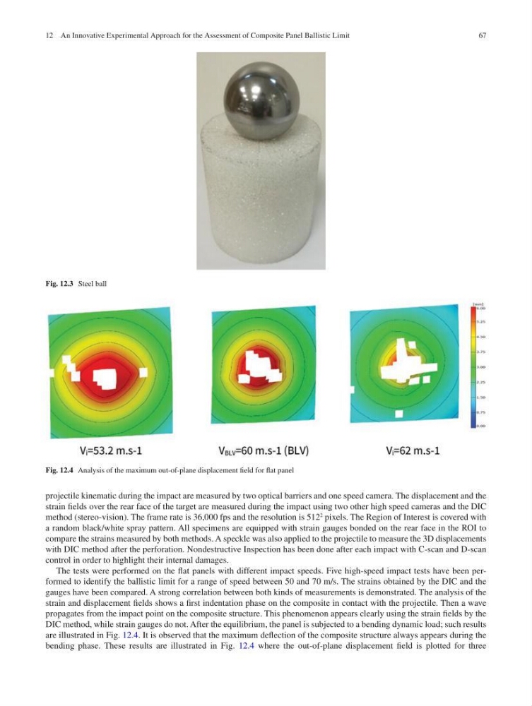
Fig. 12.4 Analysis of the maximum out-of-plane displacement field for flat panel
projectile kinematic during the impact are measured by two optical barriers and one speed camera. The displacement and the
strain fields over the rear face of the target are measured during the impact using two other high speed cameras and the DIC
method (stereo-vision). The frame rate is 36,000 fps and the resolution is 512
2
pixels. The Region of Interest is covered with
a random black/white spray pattern. All specimens are equipped with strain gauges bonded on the rear face in the ROI to
compare the strains measured by both methods. A speckle was also applied to the projectile to measure the 3D displacements
with DIC method after the perforation. Nondestructive Inspection has been done after each impact with C-scan and D-scan
control in order to highlight their internal damages.
The tests were performed on the flat panels with different impact speeds. Five high-speed impact tests have been performed to identify the ballistic limit for a range of speed between 50 and 70 m/s. The strains obtained by the DIC and the
gauges have been compared. A strong correlation between both kinds of measurements is demonstrated. The analysis of the
strain and displacement fields shows a first indentation phase on the composite in contact with the projectile. Then a wave
propagates from the impact point on the composite structure. This phenomenon appears clearly using the strain fields by the
DIC method, while strain gauges do not. After the equilibrium, the panel is subjected to a bending dynamic load; such results
are illustrated in Fig. 12.4. It is observed that the maximum deflection of the composite structure always appears during the
bending phase. These results are illustrated in Fig. 12.4 where the out-of-plane displacement field is plotted for three
12 An Innovative Experimental Approach for the Assessment of Composite Panel Ballistic Limit
Fig. 12.3 Steel ball
Fig. 12.4 Analysis of the maximum out-of-plane displacement field for flat panel
projectile kinematic during the impact are measured by two optical barriers and one speed camera. The displacement and the
strain fields over the rear face of the target are measured during the impact using two other high speed cameras and the DIC
method (stereo-vision). The frame rate is 36,000 fps and the resolution is 512
2
pixels. The Region of Interest is covered with
a random black/white spray pattern. All specimens are equipped with strain gauges bonded on the rear face in the ROI to
compare the strains measured by both methods. A speckle was also applied to the projectile to measure the 3D displacements
with DIC method after the perforation. Nondestructive Inspection has been done after each impact with C-scan and D-scan
control in order to highlight their internal damages.
The tests were performed on the flat panels with different impact speeds. Five high-speed impact tests have been performed to identify the ballistic limit for a range of speed between 50 and 70 m/s. The strains obtained by the DIC and the
gauges have been compared. A strong correlation between both kinds of measurements is demonstrated. The analysis of the
strain and displacement fields shows a first indentation phase on the composite in contact with the projectile. Then a wave
propagates from the impact point on the composite structure. This phenomenon appears clearly using the strain fields by the
DIC method, while strain gauges do not. After the equilibrium, the panel is subjected to a bending dynamic load; such results
are illustrated in Fig. 12.4. It is observed that the maximum deflection of the composite structure always appears during the
bending phase. These results are illustrated in Fig. 12.4 where the out-of-plane displacement field is plotted for three
12 An Innovative Experimental Approach for the Assessment of Composite Panel Ballistic Limit