

4.4 Constitutive Relations for Macro-fiber Composites
67
Here ˘
σ , ˘
ε denote the stress and strain vectors, ˘
c is the elasticity constant matrix.
Furthermore, ˘
D, ˘
E, ˘
e and ˘
χ represent the electric displacement vector, the electric
field vector, the piezoelectric constant matrix and the dielectric constant matrix,
respectively, among which ˘
e depends strongly on the structure of MFC materials.
4.4.3 Piezo Constants for MFC-d31 Type
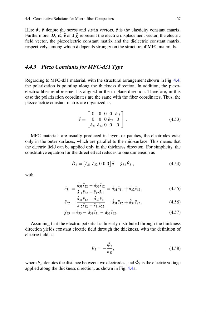
Regarding to MFC-d31 material, with the structural arrangement shown in Fig. 4.4,
the polarization is pointing along the thickness direction. In addition, the piezoelectric fiber reinforcement is aligned in the in-plane direction. Therefore, in this
case the polarization coordinates are the same with the fiber coordinates. Thus, the
piezoelectric constant matrix are organized as
˘
e =
⎡
⎣
0 0 0 0 ˘
e 15
0 0 0 ˘
e 24 0
˘
e 31 ˘
e 32 0 0 0
⎤
⎦ .
(4.53)
MFC materials are usually produced in layers or patches, the electrodes exist
only in the outer surfaces, which are parallel to the mid-surface. This means that
the electric field can be applied only in the thickness direction. For simplicity, the
constitutive equation for the direct effect reduces to one dimension as
˘
D 3 =
˘
e 31 ˘
e 32 0 0 0
˘
ε + ˘
χ 33 ˘
E 3 ,
(4.54)
with
˘
e 31 =
˘
d 31 ˘
s 22 − ˘
d 32 ˘
s 12
˘
s 11 ˘
s 22 − ˘
s 12 ˘
s 12
= ˘
d 31 ˘
c 11 + ˘
d 32 ˘
c 12 ,
(4.55)
˘
e 32 =
˘
d 31 ˘
s 12 − ˘
d 32 ˘
s 11
˘
s 12 ˘
s 12 − ˘
s 11 ˘
s 22
= ˘
d 31 ˘
c 12 + ˘
d 32 ˘
c 22 ,
(4.56)
˘
χ 33 = ˘
33 − ˘
d 31 ˘
e 31 − ˘
d 32 ˘
e 32 ,
(4.57)
Assuming that the electric potential is linearly distributed through the thickness
direction yields constant electric field through the thickness, with the definition of
electric field as
˘
E 3 = −
˘
Φ 3
h E
,
(4.58)
where h E denotes the distance between two electrodes, and ˘
Φ 3 is the electric voltage
applied along the thickness direction, as shown in Fig. 4.4a.
67
Here ˘
σ , ˘
ε denote the stress and strain vectors, ˘
c is the elasticity constant matrix.
Furthermore, ˘
D, ˘
E, ˘
e and ˘
χ represent the electric displacement vector, the electric
field vector, the piezoelectric constant matrix and the dielectric constant matrix,
respectively, among which ˘
e depends strongly on the structure of MFC materials.
4.4.3 Piezo Constants for MFC-d31 Type
Regarding to MFC-d31 material, with the structural arrangement shown in Fig. 4.4,
the polarization is pointing along the thickness direction. In addition, the piezoelectric fiber reinforcement is aligned in the in-plane direction. Therefore, in this
case the polarization coordinates are the same with the fiber coordinates. Thus, the
piezoelectric constant matrix are organized as
˘
e =
⎡
⎣
0 0 0 0 ˘
e 15
0 0 0 ˘
e 24 0
˘
e 31 ˘
e 32 0 0 0
⎤
⎦ .
(4.53)
MFC materials are usually produced in layers or patches, the electrodes exist
only in the outer surfaces, which are parallel to the mid-surface. This means that
the electric field can be applied only in the thickness direction. For simplicity, the
constitutive equation for the direct effect reduces to one dimension as
˘
D 3 =
˘
e 31 ˘
e 32 0 0 0
˘
ε + ˘
χ 33 ˘
E 3 ,
(4.54)
with
˘
e 31 =
˘
d 31 ˘
s 22 − ˘
d 32 ˘
s 12
˘
s 11 ˘
s 22 − ˘
s 12 ˘
s 12
= ˘
d 31 ˘
c 11 + ˘
d 32 ˘
c 12 ,
(4.55)
˘
e 32 =
˘
d 31 ˘
s 12 − ˘
d 32 ˘
s 11
˘
s 12 ˘
s 12 − ˘
s 11 ˘
s 22
= ˘
d 31 ˘
c 12 + ˘
d 32 ˘
c 22 ,
(4.56)
˘
χ 33 = ˘
33 − ˘
d 31 ˘
e 31 − ˘
d 32 ˘
e 32 ,
(4.57)
Assuming that the electric potential is linearly distributed through the thickness
direction yields constant electric field through the thickness, with the definition of
electric field as
˘
E 3 = −
˘
Φ 3
h E
,
(4.58)
where h E denotes the distance between two electrodes, and ˘
Φ 3 is the electric voltage
applied along the thickness direction, as shown in Fig. 4.4a.