

148
7 Numerical Analysis of Macro-fiber Composite Structures
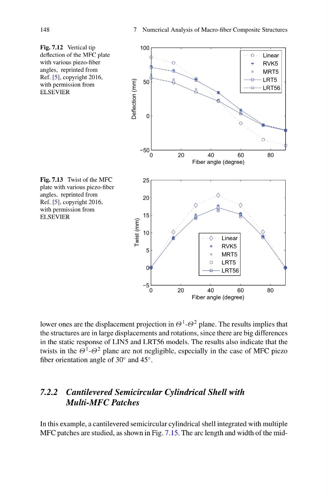
Fig. 7.12 Vertical tip
deflection of the MFC plate
with various piezo-fiber
angles, reprinted from
Ref. [5], copyright 2016,
with permission from
ELSEVIER
0
20
40
60
80
−50
0
50
100
Fiber angle (degree)
Deflection (mm)
Linear
RVK5
MRT5
LRT5
LRT56
Fig. 7.13 Twist of the MFC
plate with various piezo-fiber
angles, reprinted from
Ref. [5], copyright 2016,
with permission from
ELSEVIER
0
20
40
60
80
−5
0
5
10
15
20
25
Fiber angle (degree)
Twist (mm)
Linear
RVK5
MRT5
LRT5
LRT56
lower ones are the displacement projection in Θ
1 -Θ
2 plane. The results implies that
the structures are in large displacements and rotations, since there are big differences
in the static response of LIN5 and LRT56 models. The results also indicate that the
twists in the Θ
1 -Θ
2 plane are not negligible, especially in the case of MFC piezo
fiber orientation angle of 30
◦ and 45
◦ .
7.2.2 Cantilevered Semicircular Cylindrical Shell with
Multi-MFC Patches
In this example, a cantilevered semicircular cylindrical shell integrated with multiple
MFC patches are studied, as shown in Fig. 7.15. The arc length and width of the mid-
7 Numerical Analysis of Macro-fiber Composite Structures
Fig. 7.12 Vertical tip
deflection of the MFC plate
with various piezo-fiber
angles, reprinted from
Ref. [5], copyright 2016,
with permission from
ELSEVIER
0
20
40
60
80
−50
0
50
100
Fiber angle (degree)
Deflection (mm)
Linear
RVK5
MRT5
LRT5
LRT56
Fig. 7.13 Twist of the MFC
plate with various piezo-fiber
angles, reprinted from
Ref. [5], copyright 2016,
with permission from
ELSEVIER
0
20
40
60
80
−5
0
5
10
15
20
25
Fiber angle (degree)
Twist (mm)
Linear
RVK5
MRT5
LRT5
LRT56
lower ones are the displacement projection in Θ
1 -Θ
2 plane. The results implies that
the structures are in large displacements and rotations, since there are big differences
in the static response of LIN5 and LRT56 models. The results also indicate that the
twists in the Θ
1 -Θ
2 plane are not negligible, especially in the case of MFC piezo
fiber orientation angle of 30
◦ and 45
◦ .
7.2.2 Cantilevered Semicircular Cylindrical Shell with
Multi-MFC Patches
In this example, a cantilevered semicircular cylindrical shell integrated with multiple
MFC patches are studied, as shown in Fig. 7.15. The arc length and width of the mid-