

7.1 Linear Analysis of MFC Structures
139
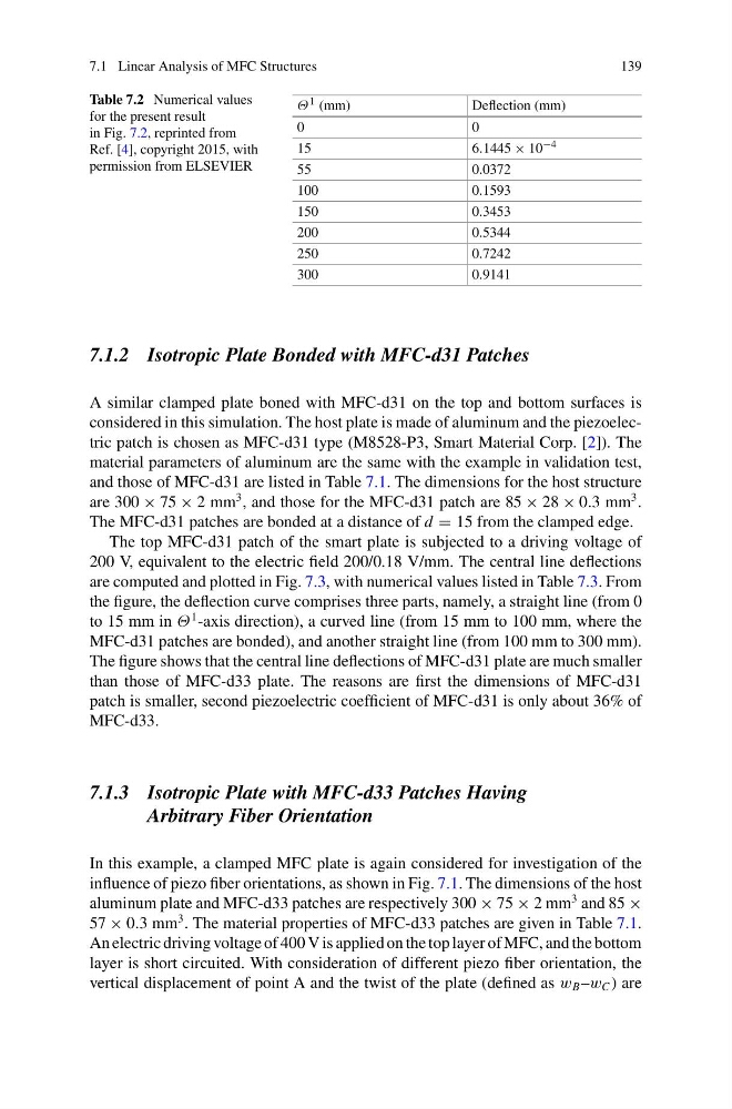
Table 7.2 Numerical values
for the present result
in Fig. 7.2, reprinted from
Ref. [4], copyright 2015, with
permission from ELSEVIER
Θ 1 (mm)
Deflection (mm)
0
0
15
6.1445 × 10 −4
55
0.0372
100
0.1593
150
0.3453
200
0.5344
250
0.7242
300
0.9141
7.1.2 Isotropic Plate Bonded with MFC-d31 Patches
A similar clamped plate boned with MFC-d31 on the top and bottom surfaces is
considered in this simulation. The host plate is made of aluminum and the piezoelectric patch is chosen as MFC-d31 type (M8528-P3, Smart Material Corp. [2]). The
material parameters of aluminum are the same with the example in validation test,
and those of MFC-d31 are listed in Table 7.1. The dimensions for the host structure
are 300 × 75 × 2 mm
3 , and those for the MFC-d31 patch are 85 × 28 × 0.3 mm
3 .
The MFC-d31 patches are bonded at a distance of d = 15 from the clamped edge.
The top MFC-d31 patch of the smart plate is subjected to a driving voltage of
200 V, equivalent to the electric field 200/0.18 V/mm. The central line deflections
are computed and plotted in Fig. 7.3, with numerical values listed in Table 7.3. From
the figure, the deflection curve comprises three parts, namely, a straight line (from 0
to 15 mm in Θ
1 -axis direction), a curved line (from 15 mm to 100 mm, where the
MFC-d31 patches are bonded), and another straight line (from 100 mm to 300 mm).
The figure shows that the central line deflections of MFC-d31 plate are much smaller
than those of MFC-d33 plate. The reasons are first the dimensions of MFC-d31
patch is smaller, second piezoelectric coefficient of MFC-d31 is only about 36% of
MFC-d33.
7.1.3 Isotropic Plate with MFC-d33 Patches Having
Arbitrary Fiber Orientation
In this example, a clamped MFC plate is again considered for investigation of the
influence of piezo fiber orientations, as shown in Fig. 7.1. The dimensions of the host
aluminum plate and MFC-d33 patches are respectively 300 × 75 × 2 mm
3 and 85 ×
57 × 0.3 mm
3 . The material properties of MFC-d33 patches are given in Table 7.1.
An electric driving voltage of 400 V is applied on the top layer of MFC, and the bottom
layer is short circuited. With consideration of different piezo fiber orientation, the
vertical displacement of point A and the twist of the plate (defined as w B –w C ) are
139
Table 7.2 Numerical values
for the present result
in Fig. 7.2, reprinted from
Ref. [4], copyright 2015, with
permission from ELSEVIER
Θ 1 (mm)
Deflection (mm)
0
0
15
6.1445 × 10 −4
55
0.0372
100
0.1593
150
0.3453
200
0.5344
250
0.7242
300
0.9141
7.1.2 Isotropic Plate Bonded with MFC-d31 Patches
A similar clamped plate boned with MFC-d31 on the top and bottom surfaces is
considered in this simulation. The host plate is made of aluminum and the piezoelectric patch is chosen as MFC-d31 type (M8528-P3, Smart Material Corp. [2]). The
material parameters of aluminum are the same with the example in validation test,
and those of MFC-d31 are listed in Table 7.1. The dimensions for the host structure
are 300 × 75 × 2 mm
3 , and those for the MFC-d31 patch are 85 × 28 × 0.3 mm
3 .
The MFC-d31 patches are bonded at a distance of d = 15 from the clamped edge.
The top MFC-d31 patch of the smart plate is subjected to a driving voltage of
200 V, equivalent to the electric field 200/0.18 V/mm. The central line deflections
are computed and plotted in Fig. 7.3, with numerical values listed in Table 7.3. From
the figure, the deflection curve comprises three parts, namely, a straight line (from 0
to 15 mm in Θ
1 -axis direction), a curved line (from 15 mm to 100 mm, where the
MFC-d31 patches are bonded), and another straight line (from 100 mm to 300 mm).
The figure shows that the central line deflections of MFC-d31 plate are much smaller
than those of MFC-d33 plate. The reasons are first the dimensions of MFC-d31
patch is smaller, second piezoelectric coefficient of MFC-d31 is only about 36% of
MFC-d33.
7.1.3 Isotropic Plate with MFC-d33 Patches Having
Arbitrary Fiber Orientation
In this example, a clamped MFC plate is again considered for investigation of the
influence of piezo fiber orientations, as shown in Fig. 7.1. The dimensions of the host
aluminum plate and MFC-d33 patches are respectively 300 × 75 × 2 mm
3 and 85 ×
57 × 0.3 mm
3 . The material properties of MFC-d33 patches are given in Table 7.1.
An electric driving voltage of 400 V is applied on the top layer of MFC, and the bottom
layer is short circuited. With consideration of different piezo fiber orientation, the
vertical displacement of point A and the twist of the plate (defined as w B –w C ) are