

6.3 Geometrically Nonlinear Analysis of Smart Structures
121
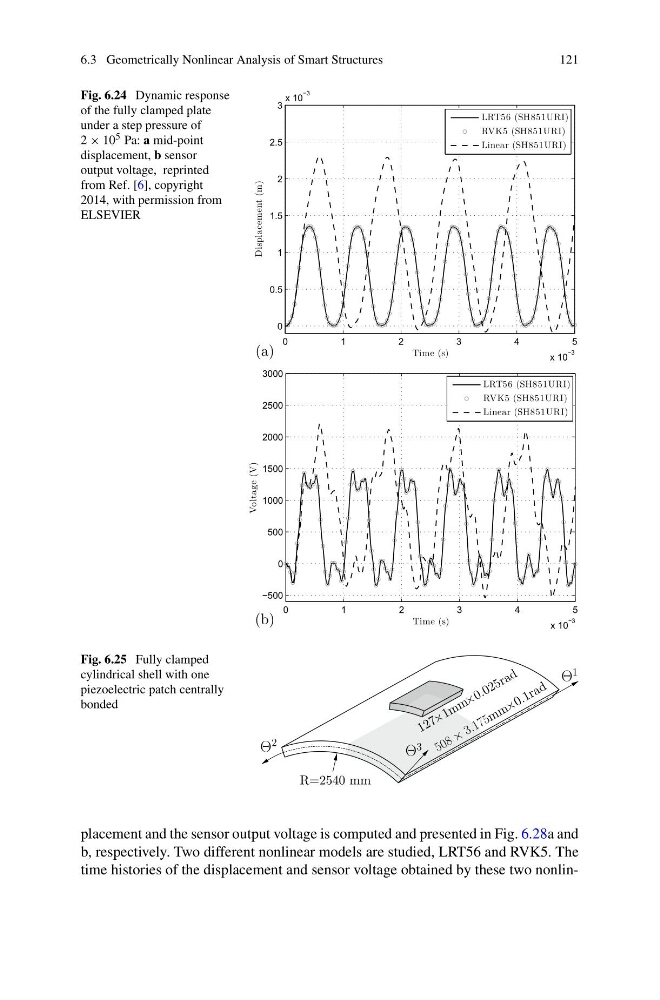
Fig. 6.24 Dynamic response
of the fully clamped plate
under a step pressure of
2 × 10 5 Pa: a mid-point
displacement, b sensor
output voltage, reprinted
from Ref. [6], copyright
2014, with permission from
ELSEVIER
(a)
0
1
2
3
4
5
x 10
−3
0
0.5
1
1.5
2
2.5
3
x 10
−3
Time (s)
Displacement (m)
LRT56 (SH851URI)
RVK5 (SH851URI)
Linear (SH851URI)
(b)
0
1
2
3
4
5
x 10
−3
−500
0
500
1000
1500
2000
2500
3000
Time (s)
Voltage (V)
LRT56 (SH851URI)
RVK5 (SH851URI)
Linear (SH851URI)
Fig. 6.25 Fully clamped
cylindrical shell with one
piezoelectric patch centrally
bonded
R=2540 mm
Θ
2
Θ
3
Θ
1
1 2 7 × 1 m m × 0 . 0 2 5 r a d
5 0 8 ×
3 . 1 7 5 m m × 0 . 1 r a d
placement and the sensor output voltage is computed and presented in Fig. 6.28a and
b, respectively. Two different nonlinear models are studied, LRT56 and RVK5. The
time histories of the displacement and sensor voltage obtained by these two nonlin-
121
Fig. 6.24 Dynamic response
of the fully clamped plate
under a step pressure of
2 × 10 5 Pa: a mid-point
displacement, b sensor
output voltage, reprinted
from Ref. [6], copyright
2014, with permission from
ELSEVIER
(a)
0
1
2
3
4
5
x 10
−3
0
0.5
1
1.5
2
2.5
3
x 10
−3
Time (s)
Displacement (m)
LRT56 (SH851URI)
RVK5 (SH851URI)
Linear (SH851URI)
(b)
0
1
2
3
4
5
x 10
−3
−500
0
500
1000
1500
2000
2500
3000
Time (s)
Voltage (V)
LRT56 (SH851URI)
RVK5 (SH851URI)
Linear (SH851URI)
Fig. 6.25 Fully clamped
cylindrical shell with one
piezoelectric patch centrally
bonded
R=2540 mm
Θ
2
Θ
3
Θ
1
1 2 7 × 1 m m × 0 . 0 2 5 r a d
5 0 8 ×
3 . 1 7 5 m m × 0 . 1 r a d
placement and the sensor output voltage is computed and presented in Fig. 6.28a and
b, respectively. Two different nonlinear models are studied, LRT56 and RVK5. The
time histories of the displacement and sensor voltage obtained by these two nonlin-