

6.3 Geometrically Nonlinear Analysis of Smart Structures
111
Fig. 6.14 Static response of
angle-ply laminated panel
with thickness of 6.3 mm
and stacking sequences
[45 ◦ / − 45 ◦ ] and
[−45 ◦ /45 ◦ ]
0
5
10
15
20
25
30
35
−0.2
0
0.2
0.4
0.6
0.8
1
Central deflection (mm)
Central force (KN)
[45/-45], LRT56 (mesh 4x4 SH85URI)
[45/-45], MRT5 (mesh 4x4 SH85URI)
[-45/45], LRT56 (mesh 4x4 SH85URI)
[-45/45], MRT5 (mesh 4x4 SH85URI)
Fig. 6.15 Cantilevered
beam with one piezoelectric
patch bonded
Θ
1
Θ
3
Θ
2
P Z T (6 0 × 1 5 × 1 m m )
6 0 m m
S t e e l( 3 0 0 × 1 5 × 1 m m )
6.3 Geometrically Nonlinear Analysis of Smart Structures
6.3.1 Cantilevered Smart Beam
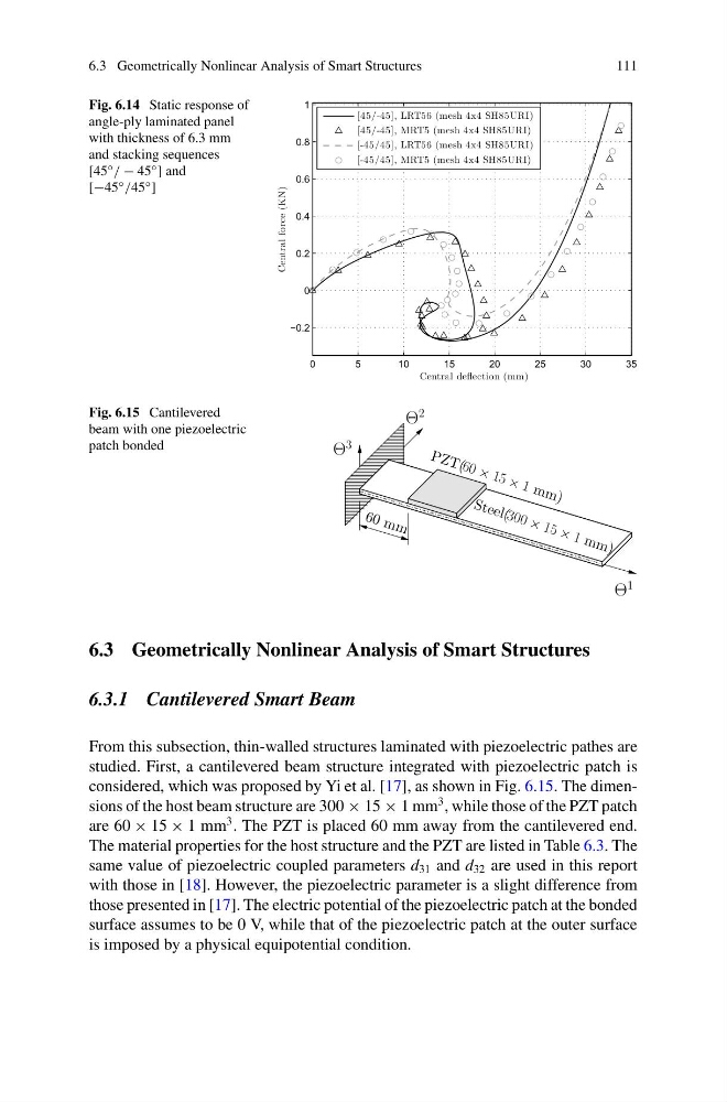
From this subsection, thin-walled structures laminated with piezoelectric pathes are
studied. First, a cantilevered beam structure integrated with piezoelectric patch is
considered, which was proposed by Yi et al. [17], as shown in Fig. 6.15. The dimensions of the host beam structure are 300 × 15 × 1 mm
3 , while those of the PZT patch
are 60 × 15 × 1 mm
3 . The PZT is placed 60 mm away from the cantilevered end.
The material properties for the host structure and the PZT are listed in Table 6.3. The
same value of piezoelectric coupled parameters d 31 and d 32 are used in this report
with those in [18]. However, the piezoelectric parameter is a slight difference from
those presented in [17]. The electric potential of the piezoelectric patch at the bonded
surface assumes to be 0 V, while that of the piezoelectric patch at the outer surface
is imposed by a physical equipotential condition.
111
Fig. 6.14 Static response of
angle-ply laminated panel
with thickness of 6.3 mm
and stacking sequences
[45 ◦ / − 45 ◦ ] and
[−45 ◦ /45 ◦ ]
0
5
10
15
20
25
30
35
−0.2
0
0.2
0.4
0.6
0.8
1
Central deflection (mm)
Central force (KN)
[45/-45], LRT56 (mesh 4x4 SH85URI)
[45/-45], MRT5 (mesh 4x4 SH85URI)
[-45/45], LRT56 (mesh 4x4 SH85URI)
[-45/45], MRT5 (mesh 4x4 SH85URI)
Fig. 6.15 Cantilevered
beam with one piezoelectric
patch bonded
Θ
1
Θ
3
Θ
2
P Z T (6 0 × 1 5 × 1 m m )
6 0 m m
S t e e l( 3 0 0 × 1 5 × 1 m m )
6.3 Geometrically Nonlinear Analysis of Smart Structures
6.3.1 Cantilevered Smart Beam
From this subsection, thin-walled structures laminated with piezoelectric pathes are
studied. First, a cantilevered beam structure integrated with piezoelectric patch is
considered, which was proposed by Yi et al. [17], as shown in Fig. 6.15. The dimensions of the host beam structure are 300 × 15 × 1 mm
3 , while those of the PZT patch
are 60 × 15 × 1 mm
3 . The PZT is placed 60 mm away from the cantilevered end.
The material properties for the host structure and the PZT are listed in Table 6.3. The
same value of piezoelectric coupled parameters d 31 and d 32 are used in this report
with those in [18]. However, the piezoelectric parameter is a slight difference from
those presented in [17]. The electric potential of the piezoelectric patch at the bonded
surface assumes to be 0 V, while that of the piezoelectric patch at the outer surface
is imposed by a physical equipotential condition.