

114
7 Virtual testing approach for sandwich panel joints
These include, core shear buckling, face shear damage and face to potting adhesive
debonding. In addition, there is a contact between specimen and fixture, which may
have to be implemented as well in order to represent the reference tests appropriately.
This is considered as high degree of non-linearity thus pointing towards the application
of the explicit method, despite the quasi-static nature of the reference test. Based on
the available literature and past experience, no additional performance study is performed. Figure 83 illustrates the defined model framework based on the previously introduced flow chart.
7.4 Phase 3 - Model development
The objective of the model development phase is the implementation of the reference
test as FE-simulation and thus as virtual test. This requires a complete set of material
and modelling parameters, which adequately represent the physical test configuration.
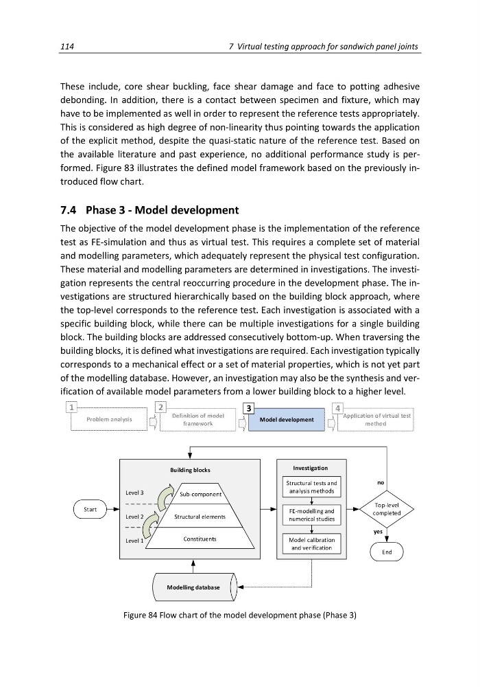
These material and modelling parameters are determined in investigations. The investigation represents the central reoccurring procedure in the development phase. The investigations are structured hierarchically based on the building block approach, where
the top-level corresponds to the reference test. Each investigation is associated with a
specific building block, while there can be multiple investigations for a single building
block. The building blocks are addressed consecutively bottom-up. When traversing the
building blocks, it is defined what investigations are required. Each investigation typically
corresponds to a mechanical effect or a set of material properties, which is not yet part
of the modelling database. However, an investigation may also be the synthesis and verification of available model parameters from a lower building block to a higher level.
Structural tests and
analysis methods
FE-modelling and
numerical studies
Model calibration
and verification
Building blocks
Investigation
Start
End
yes
Top-level
completed
no
Modelling database
Constituents
Structural elements
Sub-component
Level 1
Level 2
Level 3
Problem analysis
Definition of model
framework
Model development
Application of virtual test
method
1
2
3
4
Figure 84 Flow chart of the model development phase (Phase 3)
7 Virtual testing approach for sandwich panel joints
These include, core shear buckling, face shear damage and face to potting adhesive
debonding. In addition, there is a contact between specimen and fixture, which may
have to be implemented as well in order to represent the reference tests appropriately.
This is considered as high degree of non-linearity thus pointing towards the application
of the explicit method, despite the quasi-static nature of the reference test. Based on
the available literature and past experience, no additional performance study is performed. Figure 83 illustrates the defined model framework based on the previously introduced flow chart.
7.4 Phase 3 - Model development
The objective of the model development phase is the implementation of the reference
test as FE-simulation and thus as virtual test. This requires a complete set of material
and modelling parameters, which adequately represent the physical test configuration.
These material and modelling parameters are determined in investigations. The investigation represents the central reoccurring procedure in the development phase. The investigations are structured hierarchically based on the building block approach, where
the top-level corresponds to the reference test. Each investigation is associated with a
specific building block, while there can be multiple investigations for a single building
block. The building blocks are addressed consecutively bottom-up. When traversing the
building blocks, it is defined what investigations are required. Each investigation typically
corresponds to a mechanical effect or a set of material properties, which is not yet part
of the modelling database. However, an investigation may also be the synthesis and verification of available model parameters from a lower building block to a higher level.
Structural tests and
analysis methods
FE-modelling and
numerical studies
Model calibration
and verification
Building blocks
Investigation
Start
End
yes
Top-level
completed
no
Modelling database
Constituents
Structural elements
Sub-component
Level 1
Level 2
Level 3
Problem analysis
Definition of model
framework
Model development
Application of virtual test
method
1
2
3
4
Figure 84 Flow chart of the model development phase (Phase 3)