

7.3 Phase 2 - Definition of model framework
111
Quasi 3D-continuum
(axisymmetric)
3D-continuum
Detailed meso-scale
Start
2D-shell
Definition of level of detail
Selection of time integration
Explicit
Implicit
In-plane damage
Symmetry about panel plane
Out-of-plane damage
Axisymmetric loading
Isotropic materials
In-plane and out-ofplane damage
Orthotropic materials
Large core deformation
with multiaxial loading
Optimization of cellular
cores
More than two nonlinear effects
High loading rates
Up to two non-linear
effects
Quasi-static loading
Framework
suitable
Preliminary evaluation
no
yes
End
Convergence
Compuational effort
Problem analysis
Definition of model
framework
Model development
Application of virtual test
method
1
2
3
4
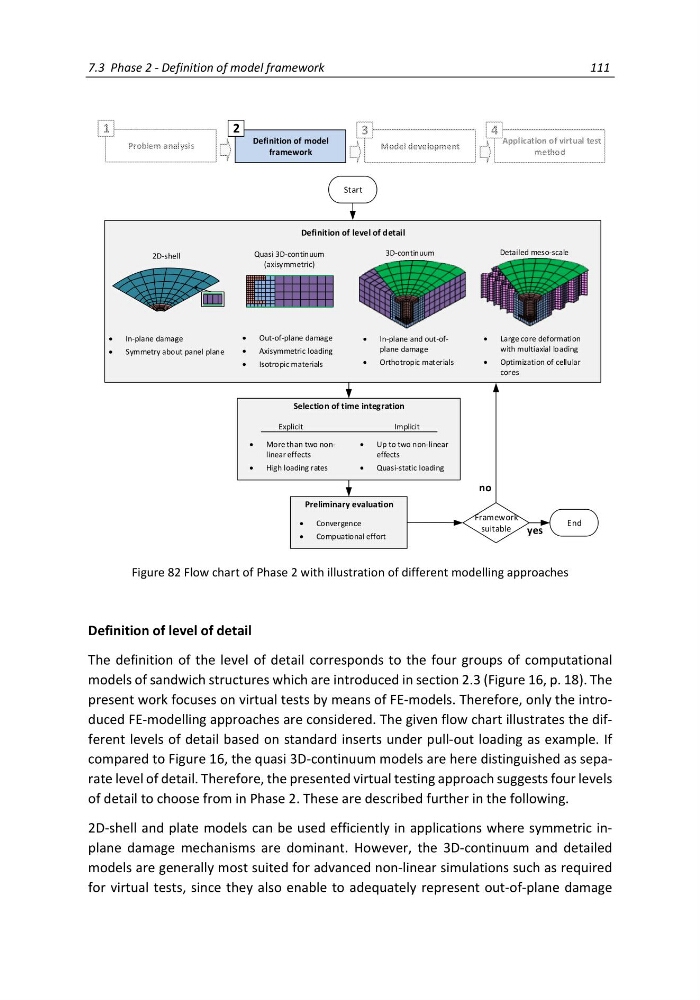
Figure 82 Flow chart of Phase 2 with illustration of different modelling approaches
Definition of level of detail
The definition of the level of detail corresponds to the four groups of computational
models of sandwich structures which are introduced in section 2.3 (Figure 16, p. 18). The
present work focuses on virtual tests by means of FE-models. Therefore, only the introduced FE-modelling approaches are considered. The given flow chart illustrates the different levels of detail based on standard inserts under pull-out loading as example. If
compared to Figure 16, the quasi 3D-continuum models are here distinguished as separate level of detail. Therefore, the presented virtual testing approach suggests four levels
of detail to choose from in Phase 2. These are described further in the following.
2D-shell and plate models can be used efficiently in applications where symmetric inplane damage mechanisms are dominant. However, the 3D-continuum and detailed
models are generally most suited for advanced non-linear simulations such as required
for virtual tests, since they also enable to adequately represent out-of-plane damage
111
Quasi 3D-continuum
(axisymmetric)
3D-continuum
Detailed meso-scale
Start
2D-shell
Definition of level of detail
Selection of time integration
Explicit
Implicit
In-plane damage
Symmetry about panel plane
Out-of-plane damage
Axisymmetric loading
Isotropic materials
In-plane and out-ofplane damage
Orthotropic materials
Large core deformation
with multiaxial loading
Optimization of cellular
cores
More than two nonlinear effects
High loading rates
Up to two non-linear
effects
Quasi-static loading
Framework
suitable
Preliminary evaluation
no
yes
End
Convergence
Compuational effort
Problem analysis
Definition of model
framework
Model development
Application of virtual test
method
1
2
3
4
Figure 82 Flow chart of Phase 2 with illustration of different modelling approaches
Definition of level of detail
The definition of the level of detail corresponds to the four groups of computational
models of sandwich structures which are introduced in section 2.3 (Figure 16, p. 18). The
present work focuses on virtual tests by means of FE-models. Therefore, only the introduced FE-modelling approaches are considered. The given flow chart illustrates the different levels of detail based on standard inserts under pull-out loading as example. If
compared to Figure 16, the quasi 3D-continuum models are here distinguished as separate level of detail. Therefore, the presented virtual testing approach suggests four levels
of detail to choose from in Phase 2. These are described further in the following.
2D-shell and plate models can be used efficiently in applications where symmetric inplane damage mechanisms are dominant. However, the 3D-continuum and detailed
models are generally most suited for advanced non-linear simulations such as required
for virtual tests, since they also enable to adequately represent out-of-plane damage