

100
6 Mechanical characterization on sub-component level
wrinkling due to core crushing on the compression side of the insert. The experimental
results are described in more detail in the problem analysis step of the virtual testing
approach, which is introduced in the following chapter.
a)
b)
c)
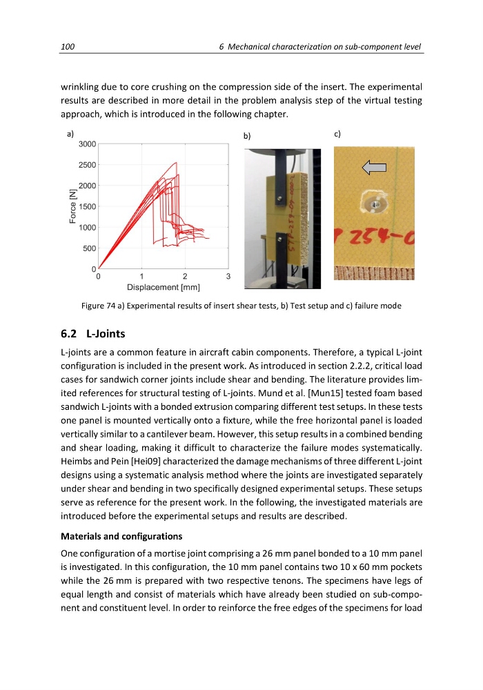
Figure 74 a) Experimental results of insert shear tests, b) Test setup and c) failure mode
6.2 L-Joints
L-joints are a common feature in aircraft cabin components. Therefore, a typical L-joint
configuration is included in the present work. As introduced in section 2.2.2, critical load
cases for sandwich corner joints include shear and bending. The literature provides limited references for structural testing of L-joints. Mund et al. [Mun15] tested foam based
sandwich L-joints with a bonded extrusion comparing different test setups. In these tests
one panel is mounted vertically onto a fixture, while the free horizontal panel is loaded
vertically similar to a cantilever beam. However, this setup results in a combined bending
and shear loading, making it difficult to characterize the failure modes systematically.
Heimbs and Pein [Hei09] characterized the damage mechanisms of three different L-joint
designs using a systematic analysis method where the joints are investigated separately
under shear and bending in two specifically designed experimental setups. These setups
serve as reference for the present work. In the following, the investigated materials are
introduced before the experimental setups and results are described.
Materials and configurations
One configuration of a mortise joint comprising a 26 mm panel bonded to a 10 mm panel
is investigated. In this configuration, the 10 mm panel contains two 10 x 60 mm pockets
while the 26 mm is prepared with two respective tenons. The specimens have legs of
equal length and consist of materials which have already been studied on sub-component and constituent level. In order to reinforce the free edges of the specimens for load
6 Mechanical characterization on sub-component level
wrinkling due to core crushing on the compression side of the insert. The experimental
results are described in more detail in the problem analysis step of the virtual testing
approach, which is introduced in the following chapter.
a)
b)
c)
Figure 74 a) Experimental results of insert shear tests, b) Test setup and c) failure mode
6.2 L-Joints
L-joints are a common feature in aircraft cabin components. Therefore, a typical L-joint
configuration is included in the present work. As introduced in section 2.2.2, critical load
cases for sandwich corner joints include shear and bending. The literature provides limited references for structural testing of L-joints. Mund et al. [Mun15] tested foam based
sandwich L-joints with a bonded extrusion comparing different test setups. In these tests
one panel is mounted vertically onto a fixture, while the free horizontal panel is loaded
vertically similar to a cantilever beam. However, this setup results in a combined bending
and shear loading, making it difficult to characterize the failure modes systematically.
Heimbs and Pein [Hei09] characterized the damage mechanisms of three different L-joint
designs using a systematic analysis method where the joints are investigated separately
under shear and bending in two specifically designed experimental setups. These setups
serve as reference for the present work. In the following, the investigated materials are
introduced before the experimental setups and results are described.
Materials and configurations
One configuration of a mortise joint comprising a 26 mm panel bonded to a 10 mm panel
is investigated. In this configuration, the 10 mm panel contains two 10 x 60 mm pockets
while the 26 mm is prepared with two respective tenons. The specimens have legs of
equal length and consist of materials which have already been studied on sub-component and constituent level. In order to reinforce the free edges of the specimens for load