

84
3 Continuum Mechanics and Nonlinear Elasticity
and carrying out the matrix multiplication gives
¯
E 11 = E 11 cos
2 θ + 2E 12 sin θ cos θ + E 22 sin
2 θ
¯
E 22 = E 11 sin
2 θ − 2E 12 sin θ cos θ + E 22 cos
2 θ
¯
E 12 = ¯
E 21 = (E 22 − E 11 ) sin θ cos θ + E 12 (cos
2 θ − sin
2 θ).
(3.61)
These relations are equivalent to those found in standard books on mechanics of
materials, but they often are written in terms of sin 2θ and cos 2θ using trigonometric
identities.
Principal Strains To illustrate the main ideas, consider the special case of the 2D
strain transformation relations (3.61) with E 11 = E 22 = E 0 and E 12 = E 0 /2, i.e.,
¯
E 11 = ¯
E 22 = E 0 (1 + sin θ cos θ)
¯
E 12 =
1
2 E 0 (cos
2 θ − sin
2 θ).
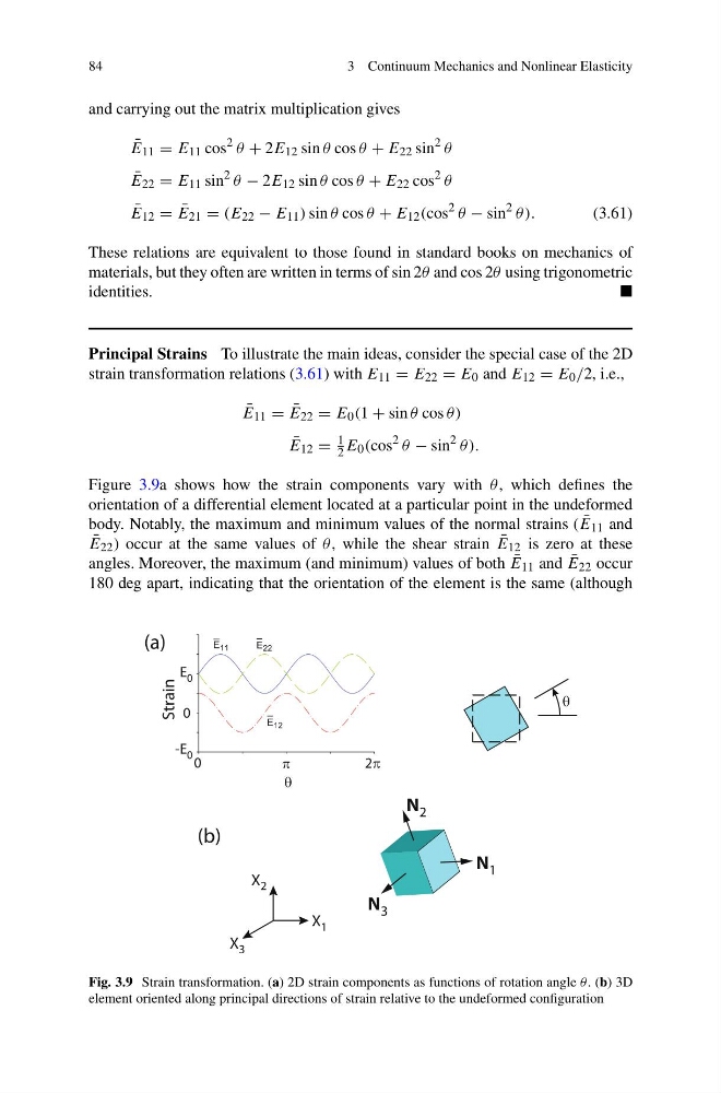
Figure 3.9a shows how the strain components vary with θ , which defines the
orientation of a differential element located at a particular point in the undeformed
body. Notably, the maximum and minimum values of the normal strains ( ¯
E 11 and
¯
E 22 ) occur at the same values of θ , while the shear strain ¯
E 12 is zero at these
angles. Moreover, the maximum (and minimum) values of both ¯
E 11 and ¯
E 22 occur
180 deg apart, indicating that the orientation of the element is the same (although
θ
0
2π
π
E 0
0
-E 0
Strain
θ
N 1
N 2
N 3
X 1
X 2
X 3
(a)
(b)
Fig. 3.9 Strain transformation. (a) 2D strain components as functions of rotation angle θ. (b) 3D
element oriented along principal directions of strain relative to the undeformed configuration
3 Continuum Mechanics and Nonlinear Elasticity
and carrying out the matrix multiplication gives
¯
E 11 = E 11 cos
2 θ + 2E 12 sin θ cos θ + E 22 sin
2 θ
¯
E 22 = E 11 sin
2 θ − 2E 12 sin θ cos θ + E 22 cos
2 θ
¯
E 12 = ¯
E 21 = (E 22 − E 11 ) sin θ cos θ + E 12 (cos
2 θ − sin
2 θ).
(3.61)
These relations are equivalent to those found in standard books on mechanics of
materials, but they often are written in terms of sin 2θ and cos 2θ using trigonometric
identities.
Principal Strains To illustrate the main ideas, consider the special case of the 2D
strain transformation relations (3.61) with E 11 = E 22 = E 0 and E 12 = E 0 /2, i.e.,
¯
E 11 = ¯
E 22 = E 0 (1 + sin θ cos θ)
¯
E 12 =
1
2 E 0 (cos
2 θ − sin
2 θ).
Figure 3.9a shows how the strain components vary with θ , which defines the
orientation of a differential element located at a particular point in the undeformed
body. Notably, the maximum and minimum values of the normal strains ( ¯
E 11 and
¯
E 22 ) occur at the same values of θ , while the shear strain ¯
E 12 is zero at these
angles. Moreover, the maximum (and minimum) values of both ¯
E 11 and ¯
E 22 occur
180 deg apart, indicating that the orientation of the element is the same (although
θ
0
2π
π
E 0
0
-E 0
Strain
θ
N 1
N 2
N 3
X 1
X 2
X 3
(a)
(b)
Fig. 3.9 Strain transformation. (a) 2D strain components as functions of rotation angle θ. (b) 3D
element oriented along principal directions of strain relative to the undeformed configuration