

476
8 Morphogenesis
x
y
k
g = a
)
b
(
)
a
(
n=1
n=4
n=3
n=2
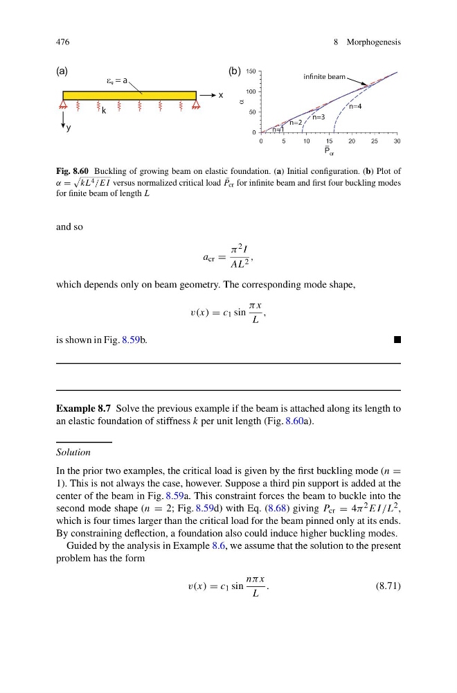
Fig. 8.60 Buckling of growing beam on elastic foundation. (a) Initial configuration. (b) Plot of
α =
kL 4 /EI versus normalized critical load ¯
P cr for infinite beam and first four buckling modes
for finite beam of length L
and so
a cr =
π 2 I
AL 2 ,
which depends only on beam geometry. The corresponding mode shape,
v(x) = c 1 sin
πx
L
,
is shown in Fig. 8.59b.
Example 8.7 Solve the previous example if the beam is attached along its length to
an elastic foundation of stiffness k per unit length (Fig. 8.60a).
Solution
In the prior two examples, the critical load is given by the first buckling mode (n =
1). This is not always the case, however. Suppose a third pin support is added at the
center of the beam in Fig. 8.59a. This constraint forces the beam to buckle into the
second mode shape (n = 2; Fig. 8.59d) with Eq. (8.68) giving P cr = 4π 2 EI /L 2 ,
which is four times larger than the critical load for the beam pinned only at its ends.
By constraining deflection, a foundation also could induce higher buckling modes.
Guided by the analysis in Example 8.6, we assume that the solution to the present
problem has the form
v(x) = c 1 sin
nπ x
L
.
(8.71)
8 Morphogenesis
x
y
k
g = a
)
b
(
)
a
(
n=1
n=4
n=3
n=2
Fig. 8.60 Buckling of growing beam on elastic foundation. (a) Initial configuration. (b) Plot of
α =
kL 4 /EI versus normalized critical load ¯
P cr for infinite beam and first four buckling modes
for finite beam of length L
and so
a cr =
π 2 I
AL 2 ,
which depends only on beam geometry. The corresponding mode shape,
v(x) = c 1 sin
πx
L
,
is shown in Fig. 8.59b.
Example 8.7 Solve the previous example if the beam is attached along its length to
an elastic foundation of stiffness k per unit length (Fig. 8.60a).
Solution
In the prior two examples, the critical load is given by the first buckling mode (n =
1). This is not always the case, however. Suppose a third pin support is added at the
center of the beam in Fig. 8.59a. This constraint forces the beam to buckle into the
second mode shape (n = 2; Fig. 8.59d) with Eq. (8.68) giving P cr = 4π 2 EI /L 2 ,
which is four times larger than the critical load for the beam pinned only at its ends.
By constraining deflection, a foundation also could induce higher buckling modes.
Guided by the analysis in Example 8.6, we assume that the solution to the present
problem has the form
v(x) = c 1 sin
nπ x
L
.
(8.71)