

474
8 Morphogenesis
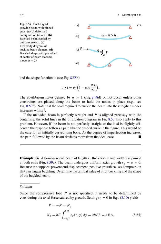
Fig. 8.59 Buckling of
growing beam with pinned
ends. (a) Undeformed
configuration (a = 0). (b)
Buckled beam caused by
uniform growth. (c)
Free-body diagram of
buckled beam element. (d)
Buckled shape with pin added
at center of beam (second
mode, n = 2)
x
Hg = a > a cr
M
P
v
P
(a)
(b)
(c)
(d)
and the shape function is (see Fig. 8.58b)
v(x) = v 0
1 − cos
πx
2L
.
The equilibrium states defined by n > 1 (Fig. 8.58d) do not occur unless other
constraints are placed along the beam to hold the nodes in place (e.g., see
Fig. 8.59d). Note that the load required to buckle the beam into these higher modes
increases with n 2 .
If the unloaded beam is perfectly straight and P is aligned precisely with the
centerline, the solid lines in the bifurcation diagram in Fig. 8.57 also apply to this
problem. However, if the beam is not perfectly straight or the load is slightly offcenter, the response follows a path like the dashed curve in the figure. This would be
the case for an initially curved long bone. As the degree of imperfection increases,
the path followed by the beam deviates more from the ideal case.
Example 8.6 A homogeneous beam of length L, thickness h, and width b is pinned
at both ends (Fig. 8.59a). The beam undergoes uniform axial growth g = a > 0.
Because the supports prevent end displacement, positive growth causes compression
that can trigger buckling. Determine the critical value of a for buckling and the shape
of the buckled beam.
Solution
Since the compressive load P is not specified, it needs to be determined by
considering the axial force caused by growth. Setting 0 = 0 in Eqs. (8.10) yields
P = −N = N g
N g = bE
h/2
−h/2
g (x, y) dy = abEh = aEA,
(8.65)
8 Morphogenesis
Fig. 8.59 Buckling of
growing beam with pinned
ends. (a) Undeformed
configuration (a = 0). (b)
Buckled beam caused by
uniform growth. (c)
Free-body diagram of
buckled beam element. (d)
Buckled shape with pin added
at center of beam (second
mode, n = 2)
x
Hg = a > a cr
M
P
v
P
(a)
(b)
(c)
(d)
and the shape function is (see Fig. 8.58b)
v(x) = v 0
1 − cos
πx
2L
.
The equilibrium states defined by n > 1 (Fig. 8.58d) do not occur unless other
constraints are placed along the beam to hold the nodes in place (e.g., see
Fig. 8.59d). Note that the load required to buckle the beam into these higher modes
increases with n 2 .
If the unloaded beam is perfectly straight and P is aligned precisely with the
centerline, the solid lines in the bifurcation diagram in Fig. 8.57 also apply to this
problem. However, if the beam is not perfectly straight or the load is slightly offcenter, the response follows a path like the dashed curve in the figure. This would be
the case for an initially curved long bone. As the degree of imperfection increases,
the path followed by the beam deviates more from the ideal case.
Example 8.6 A homogeneous beam of length L, thickness h, and width b is pinned
at both ends (Fig. 8.59a). The beam undergoes uniform axial growth g = a > 0.
Because the supports prevent end displacement, positive growth causes compression
that can trigger buckling. Determine the critical value of a for buckling and the shape
of the buckled beam.
Solution
Since the compressive load P is not specified, it needs to be determined by
considering the axial force caused by growth. Setting 0 = 0 in Eqs. (8.10) yields
P = −N = N g
N g = bE
h/2
−h/2
g (x, y) dy = abEh = aEA,
(8.65)